Wiki
Note
This is a basic view of the Wiki
3D Model library
Mechatronic
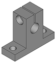
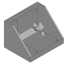
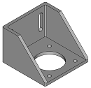
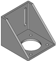
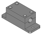
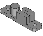
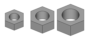
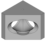
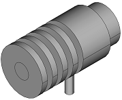
Shaft Holder
Size
Low profile: Only in size 8
Details
|
SK dimensions: dictionary for the dimensions . |
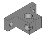
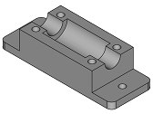
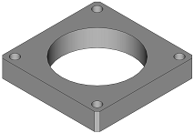
Idler Holder
Size of the profile on which it is mounted
Bolt metrics
Height
Position of the limit switch sensor
Height of the limit switch sensor
The model will be modified for greater efficiency
Details
|
Creates a holder for a IdlePulley. |
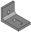
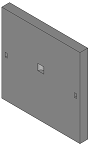
Limit Switches Holder
Type
Rail distance
Details
|
Very simple endstop holder to be attached to a alu profile and that can be adjusted . |
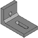
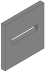
Hall stop
Width
Thikness
Metric nut
Profile size
Reinforce
Details
|
Bracket
Type: 3 options
Size first profile
Size second profile
Thickness
Metric nut first profile
Metric nut second profile
Number of nuts
Distance betwen nuts
Type of hole
Reinforcement: first type only
Flap: second type only
Distance between profiles: third type only
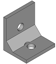
Details
|
Bracket to join 2 aluminum profiles that are perpendicular, that is, they are not on the same plane . |
|
Bracket to join 2 aluminum profiles that are perpendicular, that is, they are not on the same plane It is wide because it has 2 ears/flaps? on the sides, to attach to the perpendicular profile . |
|
Bracket to join 3 aluminum profiles that are perpendicular, that is, they are not on the same plane to the perpendicular profile . |
Motor holder
Size
Height
Thickness
Details
|
Creates a holder for a Nema motor |
Motor
Size
Height
Shaft height
Shaft radius
Shaft radius base
Shaft height base
Chamfer radius
Bolt deep
Bolt outside
Pulley pitch
Pulley teeth
Pulley top flange
Pulley bot flange
Position in axis d
Position in axis w
Position in axis h
Placement
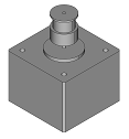
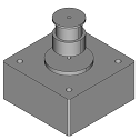
Details
|
Set composed of a Nema Motor and a pulley |
Lin bear house
Type
Details
|
Makes a housing for a linear bearing, but it is very thin and intented to be attached to one rail, instead of 2 it has to parts, the lower and the upper part . |
|
Makes a housing for a linear bearing, but it is very thin and intented to be attached to 2 rail it has to parts, the lower and the upper part . |
|
Makes a housing for a linear bearing takes the dimensions from a dictionary, like the one defined in kcomp.py it has to parts, the lower and the upper part . |
|
There are |
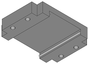
Filter holder
Length
Width
Details
|
Integration of a ShpFilterHolder object into a PartFilterHolder object, so it is a FreeCAD object that can be visualized in FreeCAD |
Tensioner
Belt hight
Base width
Thickness
Metric nut
Details
|
Set composed of the idler pulley and the tensioner |
Belt clamp
Type
Length
Width
Metric nut

Details
|
Similar to shp_topbeltclamp, but with any direction, and can have a base Creates a shape of a belt clamp. |
|
Similar to BeltClamp, but in two ways Creates a shape of a double belt clamp. |
Aluminium profile
Section
Length
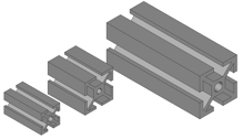
Details
|
Integration of a ShpAluProf object into a PartAluProf object, so it is a FreeCAD object that can be visualized in FreeCAD Instead of using all the arguments of ShpAluProf, it will use a dictionary |
Linear Guide
Type:
SEBW16
SEB15A
SEB8
SEB10
Position in axis d
Position in axis w
Position in axis h
Placement
Details
|
Integration of a ShpLinGuideBlock object into a PartLinGuideBlock object, so it is a FreeCAD object that can be visualized in FreeCAD Instead of using all the arguments of ShpLinGuideBlock, it will use a dictionary |
Bolts, Nuts & Washers
Type
Metric
Bolt length
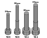

Details
|
Din 934 Nut |
|
Din 125 Washer, this is the regular washer |
|
Din 9021 Washer, this is the larger washer |
|
Din 912 bolt. |
Optical
TubeLense
Length
Placement

Details
|
Creates a componente formed by joining: the lens tube SM1LXX + SM1A2 + SM2T2, so we have: |
LCPB1M Base
Placement
Details
|
Creates a lcpb1m_base for plates side, it creates from a dictionary |
CageCube
Type:
CageCube
CageCubeHalf
Details
|
Creates a cage cube, it creates from a dictionary |
|
Dreates a half cage cube: 2 perpendicular sides, and a 45 degree angle side. |
Plate
Plate dictionary:
Lb1cm_Plate
Lb2c_Plate
Lcp01m_plate
Placement
Details
|
Creates a LB1C/M plate from thorlabs. The plate is centered |
|
Same as plate_lb2c, but it creates an object. |
|
Creates a lcp01m_plate side. |
ThLed30
Placement
Details
|
Creates the shape of a Thorlabs Led with 30.5 mm Heat Sink diameter The drawing is very rough . |
PrizLed
Placement
Details
|
Creates the shape of a Prizmatix UHP-T-Led The drawing is very rough, and the original drawing lacks many dimensions . |
BreadBoard
Length
Width
Placement
Details
|
|
Systems library
Filter Stage
Move distance
Filter length
Filter width
Base width
Tensioner stroke
Tensioner thickness
Metric nut
Motor size
Length rail motor holder
Motor holder thickness

Functions Library
fcfun
|
Adding a Nut hole (hexagonal) with a prism attached to introduce the nut. |
|
Creates a piece formed by 2 hollow cylinders |
|
Creates a piece formed by 2 hollow cylinders, and a ring on the side of the larger cylinder |
|
Creates the hole for the bolt shank and the head or the nut Tolerances have to be included |
|
Creates the hole for the bolt shank, the head and the nut. |
|
Adds a box, centered on the specified axis x and/or y, with its Placement and Rotation at zero. |
|
Adds a box, centered on the specified axis, with its Placement and Rotation at zero. |
|
Add cylinder |
|
Add cylinder, with inner hole: |
|
Same as addCylHole, but avoiding the creation of many FreeCAD objects |
|
Same as addCyl_pos, but avoiding the creation of many FreeCAD objects |
|
Add cylinder in a position. |
|
Just creates a freeCAD object of the shape, just to save one line |
|
Creates a wire (shape), that is an approximation of a generic alum profile extrusion . |
|
Similar to calc_rot, but calculates de displacement, when we don’t want to have all of the dimensions centered First vector original direction (x,y,z) is (1,0,0) Second vector original direction (x,y,z) is (0,0,-1) The arguments vec1, vec2 are tuples (x,y,z) but they may be also FreeCAD.Vectors . |
|
Having an object with an orientation defined by 2 vectors the vectors a tuples, nor FreeCAD.Vectors use the wrapper fc_calc_rot to have FreeCAD.Vector arguments First vector original direction (x,y,z) is (1,0,0) Second vector original direction (x,y,z) is (0,0,-1) we want to rotate the object in an ortoghonal direction. |
|
Calculates de rotation like calc_rot. |
|
It tells if an edge is on an axis |
|
Compare numbers that are the same but not exactly the same |
|
Same as calc_desp_ncen but using FreeCAD.Vectors arguments |
|
Same as calc_rot but using FreeCAD.Vectors arguments |
|
Just tells if a vector has 2 of the coordinates zero so it is on just a base vector |
|
Return 1 if fc1 and fc2 are paralell (colinear), 0 if they are not |
|
Very similar to fc_isparal, but in this case the arguments are normalized so, less operations to do. |
|
Return 1 if fc1 and fc2 are perpendicular, 0 if they are not |
|
Make a new object with fillet |
|
Fillet or chamfer edges of a certain length, on a certain axis and a certain coordinate |
|
Since multifuse methods needs to be done by a shape and a list, and usually I have a list that I want to fuse, I make this function to save the inconvenience of doing everytime what I will do here Fuse multiFuse |
|
same as get_bolt_end_sep, but when there is a bearing. |
|
Calculate Bolt separation |
|
gets a ‘random’ perpendicular FreeCAD.Vector |
|
Gets a list of 4 FreCAD.Vector perpendicular to one base vector fcvec can only be: * (1,0,0) * (0,1,0) * (0,0,1) * (-1,0,0) * (0,-1,0) * (0,0,-1) |
|
Gets a list of 4 FreCAD.Vector perpendicular to one vecname different from get_fclist_4perp_vecname For example: . |
|
Gets a list of 4 FreeCAD.Vector perpendicular to one base vector fcvec can only be: * (1,0,0) * (0,1,0) * (0,0,1) * (-1,0,0) * (0,-1,0) * (0,0,-1) |
|
Gets a list of 4 FreCAD.Vector perpendicular to one vecname for example: . |
|
Gets the FreeCAD.Vector of a tuple |
|
From a base vector either: (1,0,0), (0,1,0), (0,0,1), (-1,0,0), (0,-1,0), (0,0,-1) Gets its name: ‘x’, ‘y’,…. |
|
It just get ‘x’ when vecname is ‘x’ or ‘-x’, and the same for the others, because some functions receive only positive base vector |
|
Calculate the rotation from v1 to v2 the difference with previous verions, such fc_calc_rot, calc_rot, calc_rot is that it is for any vector direction. |
|
Returns a list of lists (matrix) with the 2 tangent points for each of the 2 tangent lines . |
|
Get the point of the tangent to the circle |
|
Gets a perpendicular vecname |
|
Gets the other perpendicular vecname (see get_vecname_perpend) |
|
Returns the FreeCAD.Vecor of the vector name given |
|
Get axis name renunrs the vector |
|
Similar to regpolygon_vecl but in any place and direction of the space calculates the vertexes of a regular polygon. |
|
Calculates the vertexes of a regular polygon. |
|
Rotate the camara |
|
Creates a wire (shape), that is a rectangle with rounded edges. |
|
Makes to concentric stadiums, useful for making rails for bolts the length is the same for both. |
|
Creates a wire (shape), that is an approximation of a generic alum profile extrusion. |
|
Makes a shape of 2 tangent circles (like a belt joining 2 circles). |
|
Makes a shape of a wire with 2 circles and exterior tangent lines check here It is not easy to draw it well rad1 and rad2 can be exchanged, rad1 doesnt have to be larger. |
|
Similar to addBolt, but creates a shape instead of a FreeCAD Object Creates a shape of the bolt shank and head or the nut Tolerances have to be included if you want it for making a hole |
|
Similar to shp_bolt, but it can be done in any direction Creates a shape, not a of a FreeCAD Object Creates a shape of the bolt shank and head or the nut Tolerances have to be included if you want it for making a hole |
|
Similar to addBoltNut_hole, but in any direction and creates shapes, not FreeCAD Objects Creates the hole for the bolt shank, the head and the nut. |
|
Makes a shape of a box given its 3 dimensions: width, depth and height and the direction of the height and depth dimensions. |
|
Makes a shape of a box given its 3 dimensions: width, depth and height and the direction of the height and depth dimensions. |
|
Makes a box with width, depth, heigth and then rotation will be referred to axis_w = (1,0,0) and axis_nh = (0,0,-1). |
|
Adds a shape of box, referenced on the specified axis, with its Placement and Rotation at zero. |
|
Same as shp_boxcen but with a chamfered dimension |
|
Same as shp_boxcen but with a filleted dimension |
|
The same as shp_boxcen, but when it is used to cut. |
|
Creates a box shape (cuboid) along 3 axis. |
|
Creates a shape of an electrical cable turn, in any direction But it is a shape in FreeCAD See function wire_cableturn . |
|
Fillet or chamfer edges that is a circle, the shape has to be a cylinder |
|
Same as addCylPos, but just creates the shape |
|
This is a generalization of shp_cylcenxtr. |
|
Add cylinder, can be centered on the position, and also can have an extra mm on top and bottom to make cuts |
|
Fillet or chamfer all edges of a cylinder |
|
Same as addCylHole, but just a shape |
|
This is similar to make shp_cylhole_gen but not for a whole, just an arc. |
|
This is a generalization of shp_cylholedir and shp_cylhole Makes a hollow cylinder in any position and direction, with optional extra heights, and inner and outer radius, and various locations in the cylinder |
|
This is a generalization of shp_cylholedir. |
|
Same as addCylHolePos, but just a shape Same as shp_cylhole, but this one accepts any normal |
|
Extrudes a face on any plane |
|
Extrudes a face that is on plane XY, includes a rotation |
|
Adds a shape of the profile (face) of a linear guide rail, the dent is just rough, to be able to see that it is a profile . |
|
Adds a shape of the profile (face) of a rail |
|
Fillet or chamfer edges of a certain length, on a certain axis and a certain coordinate |
|
Fillet or chamfer edges on a certain axis |
|
Fillet or chamfer edges on a certain axis and a point contained in that axis |
|
Fillet or chamfer edges on a certain axis and a list of point contained in that axis |
|
Same as shp_filletchamfer_dir, but with a list of directions |
|
Makes a shape of 2 tangent circles (like a belt joining 2 circles). |
|
Similar to NutHole, but creates a shape, in any direction. |
|
Similar to shp_regpolygon_face, but in any direction of the space makes the shape of a face of a regular polygon |
|
Makes the shape of a face of a regular polygon |
|
Makes a shape of a face of a regular polygon |
|
Similar to shp_regprism_xtr, but in any direction makes a shape of a face of a regular polygon. |
|
makes a shape of a face of a regular polygon. |
|
Same as shpRndRectWire |
|
Makes a stadium shape in any direction |
|
Same as shp_stadium_wire, but returns a face |
|
Creates a wire (shape), that is a rectangle with semicircles at a pair of opposite sides. |
|
Same as shp_stadium_wire but in any direction Also called discorectangle . |
|
Given to vectors by name ‘x’, ‘-x’, … |
|
Creates a wire following 2 pulleys and ending in a belt clamp But it is a wire in FreeCAD, has no volumen . |
|
Creates a electrical wire turn, in any direction But it is a wire in FreeCAD, has no volumen . |
|
Creates a wire of a linear guide rail, the dent is just rough, to be able to see that it is a profile |
|
Creates a wire (shape), from a list of points on the positive quadrant of XY the wire is simmetrical to both X and Y . |
UML
The UML (Unified Modeling Language) is the base diagram for software development. It is a visual description of the relationships between class objects.
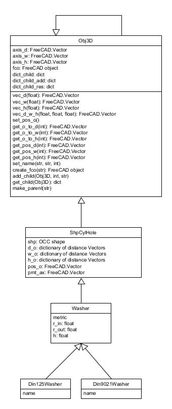
The main class will be “Obj3D” which will contain the basic information of the model:
Internal axis:
axis_d
axis_w
axis_h
Children’s dictionary:
dict_child
dict_child_sum
dict_child_res
The rest of the classes that generate the different 3D models will be part of the Obj3D class
3D model details
Mechanical
-
class
comps.Sk_dir(size, fc_axis_h=FreeCAD.Vector, fc_axis_d=FreeCAD.Vector, fc_axis_w=FreeCAD.Vector, ref_hr=1, ref_wc=1, ref_dc=1, pillow=0, pos=FreeCAD.Vector, wfco=1, tol=0.3, name='shaft_holder')[source]¶ SK dimensions: dictionary for the dimensions
mbolt: is mounting bolt. it corresponds to its metric
tbolt: is the tightening bolt.
SK12 = { 'd':12.0, 'H':37.5, 'W':42.0, 'L':14.0, 'B':32.0, 'S':5.5,
         'h':23.0, 'A':21.0, 'b': 5.0, 'g':6.0,  'I':20.0,
         'mbolt': 5, 'tbolt': 4}
        fc_axis_h
        :
     ___:___       _______________________________  tot_h
    |  ___  |
    | /   \ |      __________ HoleH = h
    | \___/ |  __
  __|       |__ /| __
 |_____________|/  __ TotD = L ___________________

      ___:___                     ___
     |  ___  |                   |...|
     | / 2 \ |                   3 1 |.....> fc_axis_d
     | \_*_/ |                   |...|
 ____|       |____               |___|
8_:5_____4_____::_|..fc_axis_w   6_7_|....... fc_axis_d
:                 :              :   :
:... tot_w .......:              :...:
                                  tot_d
- Parameters
fc_axis_h (FreeCAD.Vector) – Axis on the height direction
fc_axis_d (FreeCAD.Vector) – Axis on the depth (rod) direction
fc_axis_w (FreeCAD.Vector) – Width (perpendicular) dimension, only useful if I finally include the tightening bolt, or if ref_wc != 1
ref_hr (int) –
1: reference at the Rod Height dimension (rod center): points 1, 2, 3
0: reference at the base: points 4, 5
ref_wc (int) –
1: reference at the center on the width dimension (fc_axis_w) points: 2, 4,
0: reference at one of the bolt holes, point 5
-1: reference at one end. point 8
ref_dc (int) –
1: reference at the center of the depth dimension (fc_axis_d) points: 1,7
0: reference at one of the ends on the depth dimension points 3, 6
pillow (int) –
1 to make it the same height of a pillow block
pos (FreeCAD.Vector) – Placement
wfco (int) –
1 to create a FreeCAD Object
tol (float) – Tolerance of the axis
name (str) – FreeCAD Object name
- Returns
FreeCAD Object of a shaft holder
- Return type
FreeCAD Object
-
class
comps.PartAluProf(depth, aluprof_dict, xtr_d=0, xtr_nd=0, axis_d=FreeCAD.Vector, axis_w=FreeCAD.Vector, axis_h=FreeCAD.Vector, pos_d=0, pos_w=0, pos_h=0, pos=FreeCAD.Vector, model_type=1, name='')[source]¶ Integration of a ShpAluProf object into a PartAluProf object, so it is a FreeCAD object that can be visualized in FreeCAD Instead of using all the arguments of ShpAluProf, it will use a dictionary
- Parameters
depth (float) – (depth) length of the bar, the extrusion
aluprof_dict (dictionary) – Dictionary with all the information about the profile in kcomp.py there are some dictionaries that can be used, they are not exact – same as ShpAluProf
xtr_d (float) – If >0 it will be that extra depth (length) on the direction of axis_d
xtr_nd (float) – If >0 it will be that extra depth (length) on the opositve direction of axis_d can be V0 if pos_h = 0
axis_d (FreeCAD.Vector) – Axis along the length (depth) direction
axis_w (FreeCAD.Vector) – Axis along the width direction
axis_h (FreeCAD.Vector) – Axis along the width direction
pos_d (int) –
Location of pos along axis_d (see drawing)
0: start point, counting xtr_nd, if xtr_nd == 0 -> pos_d 0 and 1 will be the same
1: start point, not counting xtr_nd
2: middle point not conunting xtr_nd and xtr_d
3: middle point conunting xtr_nd and xtr_d
4: end point, not counting xtr_d
5: end point considering xtr_d
pos_w (int) –
Location of pos along axis_w (see drawing). Symmetric, negative indexes means the other side
0: at the center of symmetry
1: at the inner square
2: at the interior side of the outer part of the rail (thickness of the4 side)
3: at the end of the profile along axis_w
pos_h (int) – Same as pos_w
pos (FreeCAD.Vector) – Position of point defined by pos_d, pos_w, pos_h
model_type (int) –
Kind of model
1: dimensional model: it can be printed to assemble a model,but the part will not work as defined. For example, if printed this aluminum profile will not work as defined, and also, it is not exact
name (str) – Name of the object
-
class
comps.PartLinGuideBlock(block_dict, rail_dict, axis_d=FreeCAD.Vector, axis_w=FreeCAD.Vector, axis_h=FreeCAD.Vector, pos_d=0, pos_w=0, pos_h=0, pos=FreeCAD.Vector, model_type=1, name='')[source]¶ Integration of a ShpLinGuideBlock object into a PartLinGuideBlock object, so it is a FreeCAD object that can be visualized in FreeCAD Instead of using all the arguments of ShpLinGuideBlock, it will use a dictionary
- Parameters
block_dict (dictionary) – Dictionary with the information about the block
rail_dict (dictionary) – Dictionary with the information about the rail, it is not necessary, but if not provided, the block will not have the rail hole
axis_d (FreeCAD.Vector) – The axis along the depth (lenght) of the block (and rail)
axis_w (FreeCAD.Vector) – The axis along the width of the block
axis_h (FreeCAD.Vector) – The axis along the height of the block, pointing up
pos_d (int) –
Location of pos along axis_d (see drawing). Symmetric, negative indexes means the other side
0: at the center (symmetric)
1: at the bolt hole
2: at the end of the smaller part of the block
3: at the end of the end of the block
pos_w (int) –
Location of pos along axis_w (see drawing). Symmetric, negative indexes means the other side
0: at the center of symmetry
1: at the inner hole of the rail
2: at the bolt holes (it can be after the smaller part of the block)
3: at the end of the smaller part of the block
4: at the end of the end of the block
pos_h (int) –
Location of pos along axis_h (see drawing)
0: at the bottom (could make more sense to have 0 at the top instead
1: at the top of the rail hole
2: at the bottom of the bolt holes, if thruholes, same as 0
3: at the top end
4: at the bottom of the rail (not the block), if the rail has been defined
pos (FreeCAD.Vector) – Position at the point defined by pos_d, pos_w, pos_h
-
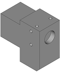
class
parts.IdlePulleyHolder(profile_size, pulleybolt_d, holdbolt_d, above_h, rail=0, mindepth=0, attach_dir='-y', endstop_side=0, endstop_posh=0, pos=FreeCAD.Vector, name='idlepulleyhold')[source]¶ Creates a holder for a IdlePulley. Usually made of bolts, washers and bearings It may include a space for a endstop It is centered at the idle pulley, but at the back, and at the profile height
       hole for endstop
      /   []: hole for the nut
    ________  ___
   ||__|    |    + above_h
___|     [] |____:__________  Z=0
   |        |      :         aluminum profile
   | O    O |      :
   |________|      + profile_size
__________________:________

     O: holes for bolts to attach to the profile

            Z
            :
     _______:__ ...
    /         /|   :
   /________ / |   :
   ||__|    |  |   + height
   |     [] |  |   :
   |        |  | ..:
   | O    O | /
   |________|/.. + depth
   :        :
   :........:
       + width

attach_dir = '-y'  enstop_side= 1     TOP VIEW


             Y
             :
             :
           __:_________
          |  :   |__| |
          | (:)       |
       ...|__:________|..... X
- Parameters
profile_size (float) – Size of the aluminum profile. 20mm, 30mm
pulleybolt_d (float) – Diameter of the bolt used to hold the pulley
holdbolt_d (float) – Diameter of the bolts used to attach this part to the aluminum profile
above_h (float) – Height of this piece above the aluminum profile
rail (float) – Posibility of having a rail instead of holes for mounting the holder. It has been made fast, so there may be bugs
mindepth (float) – If there is a minimum depth. Sometimes needed for the endstop to reach its target
attach_dir (str) – Normal vector to where the holder is attached:’x’,’-x’,’y’,’-y’ NOW ONLY -y IS SUPPORTED. YOU CAN ROTATE IT
endstop_side (int) – -1, 0, 1. Side where the enstop will be if attach_dir= ‘x’, this will be referred to the y axis if 0, there will be no endstop
endstop_h (float) – Height of the endstop. If 0 it will be just on top of the profile
pos (FreeCAD.Vector) – Object Placement
-
depth¶ Depth of the holder
- Type
float
-
width¶ Width of the holder
- Type
float
-
height¶ Height of the holder
- Type
float
-
fcoFat¶ Cad object of the compound
-
class
parts.SimpleEndstopHolder(d_endstop, rail_l=15, base_h=5.0, h=0, holder_out=2.0, mbolt_d=3.0, endstop_nut_dist=0, min_d=0, fc_axis_d=FreeCAD.Vector, fc_axis_w=FreeCAD.Vector, fc_axis_h=FreeCAD.Vector, ref_d=1, ref_w=1, ref_h=1, pos=FreeCAD.Vector, wfco=1, name='simple_enstop_holder')[source]¶ Very simple endstop holder to be attached to a alu profile and that can be adjusted
       rail_l         fc_axis_w
    ...+....           :
   :        :          :
 ______________________:
|   ________           |
|  (________)      O   |
|   ________           |-----> fc_axis_d
|  (________)      O   |
|______________________|
             :          :
             estp_tot_h

ref_d points:          fc_axis_h
                       :
1___2______3_______4___5.............     ref_h = 2
| :..........:    : : |:.....       + h
|__:________:_____:_:_|:.....base_h.:     ref_h = 1


ref_w points
                      fc_axis_w
 _____________________ :
|   ________     |    |:
|  (________) ---| 0  |:
1   ________  ---|    |:-----> fc_axis_d.
3  (________) ---| 2  |:
4________________|____|:


 _____________________ .......
| :          :    : : |:.....: endstop_nut_dist
| :..........:   :   :|:
|__:________:____:___:|:.....

           if endstop_nut_dist == 0
             just take the length+TOL of the nut
 _____________________
| :          :    : : |:
| :..........:    : : |:.....
|__:________:____:___:|:.....kcomp.NUT_D934_L[estp_bolt_d]+TOL
- Parameters
d_endstop – Dictionary of the endstop
rail_l (float) – Length of the rail, but only the internal length, not counting the arches to make the semicircles for the bolts just from semicircle center to the other semicircle center
h (float) – Total height, if 0 it will be the minimum height
base_h (float) – Height for the base (for the mounting bolts)
holder_out (float) – The endstop holder can end a little bit before to avoid it to be the endstop
mbolt_d (float) – Diameter (metric) of the mounting bolts (for the holder not for the endstop
endstop_nut_dist – Distance from the top to the endstop nut. if zero
min_d (int) – 1: make the endstop axis_d dimension the minimum
fc_axis_d (FreeCAD Vector) – Axis along the depth
fc_axis_w (FreeCAD Vector) – Axis along the width
fc_axis_h (FreeCAD Vector) – Axis along the height
ref_d (int) –
Reference (zero) of fc_axis_d
1 = at the end on the side of the rails
2 = at the circle center of one rail (closer to 1)
3 = at the circle center of the other rail, closer to endstop
4 = at the bolt of the endstop
5 = at the end of the endstop (the holder ends before that)
ref_w (int) –
Reference on fc_axis_w. it is symmetrical, only the negative side
1 = centered
2 = at one endstop bolt the other endstop bolt will be on the direction of fc_axis_w
3 = at one rail center the rail center will be on the direction of fc_axis_w
4 = at the end the end will be on the direction of fc_axis_w
ref_h (int) –
Reference (zero) of fc_axis_h
1: at the bottom
2: on top
pos (FreeCAD.Vector) – Object placement
wfco (int) – 1 a freecad object will be created
name (str) – Name of the freecad object, if created
rails can be countersunk to make space for the bolts (the) –
-
class
parts.AluProfBracketPerp(alusize_lin, alusize_perp, br_perp_thick=3.0, br_lin_thick=3.0, bolt_lin_d=3, bolt_perp_d=0, nbolts_lin=1, bolts_lin_dist=0, bolts_lin_rail=0, xtr_bolt_head=3, xtr_bolt_head_d=0, reinforce=1, fc_perp_ax=FreeCAD.Vector, fc_lin_ax=FreeCAD.Vector, pos=FreeCAD.Vector, wfco=1, name='bracket')[source]¶ Bracket to join 2 aluminum profiles that are perpendicular, that is, they are not on the same plane
   aluprof_perp (perpendicular to the bracket)
     /  / /  bracket (not drawn)
    /  / /_____
   /  / /_____/|
  /__/ /______|/ aluprof_lin (it is in line with the bracket)
  |__|/

                fc_perp_ax (is not the axis of the perpendicular
                  :         profile, but the axis of the bracket
  aluprof_perp    :         attached to the perpendicular profile
               ___:_
              |   |  \ bracket
             _|___|____\___ .........> fc_line_ax
alusize_lin +              aluprof_lin
            :_______________

                    fc_perp_ax
                     :
                     :br_perp_thick
                     .+.
                 ....:__:
                 :   |  |\
   alusize_perp  +   |  |   \
                 :   |  |______\..
                 :...|_________|..: br_lin_thick .........> fc_lin_ax
                     :.........:
- Parameters
alusize_lin (float) – Width of the aluminum profile on the line
alusize_perp (float) – Width of the perpendicular aluminum profile
br_lin_thick (float) – Thickness of the line bracket
br_perp_thick (float) – Thickness of the perpendicular bracket
bolt_lin_d (int) – Metric of the bolt 3, 4, … (integer)
bolt_perp_d (int) – Metric of the bolt 3, 4, … (integer) on the profile line if 0, the same as bolt_lin_d
nbolts_lin (int) – Number of bolts one bolt on the fc_lin_ax, number of bolts: two bolts on the fc_lin_ax
bolts_lin_dist (float) – If more than one bolt on fc_lin_ax, defines the distance between them. if zero, takes min distance
bolts_lin_rail (int) – Instead of bolt holes, it will be a rail it doesnt make sense to have number of bolts with this option it will work on 2 bolts or more. If nbolts_lin == 3, it will make a rail between them. so it will be the same to have nbolts_lin = 2 and bolts_lin_dist = 20 nbolts_lin = 3 and bolts_lin_dist = 10 The rail will be 20, and it will look the same, it will be more clear to have the first option: 2 bolts
xtr_bolt_head (float) – Extra space for the bolt head length, and making a space for it
xtr_bolt_head_d (float) – Extra space for the bolt head diameter, and making a space for it. For the wall bolt
reinforce (int) – 1, if it is reinforced on the sides of lin profile
fc_perp_ax (FreeCAD.Vector) – Axis of the bracket on the perpendicular prof, see picture
fc_lin_ax (FreeCAD.Vector) – Axis of the bracket on the aligned profile, see picture
pos (FreeCAD.Vector) – Position of the center of the bracket on the intersection
wfco (int) –
if 1: With FreeCad Object: a freecad object is created
if 0: only the shape
name (str) – Name of the freecad object, if created
-
class
parts.AluProfBracketPerpFlap(alusize_lin, alusize_perp, br_perp_thick=3.0, br_lin_thick=3.0, bolt_lin_d=3, bolt_perp_d=0, nbolts_lin=1, bolts_lin_dist=0, bolts_lin_rail=0, xtr_bolt_head=1, sunk=1, flap=1, fc_perp_ax=FreeCAD.Vector, fc_lin_ax=FreeCAD.Vector, pos=FreeCAD.Vector, wfco=1, name='bracket_flap')[source]¶ Bracket to join 2 aluminum profiles that are perpendicular, that is, they are not on the same plane It is wide because it has 2 ears/flaps? on the sides, to attach to the perpendicular profile
   aluprof_perp (perpendicular to the bracket)
     /  / /  bracket (not drawn)
    /  / /_____
   /  / /_____/|
  /__/ /______|/ aluprof_lin (it is in line with the bracket)
  |__|/


                fc_perp_ax (is not the axis of the perpendicular
                  :         profile, but the axis of the bracket
  aluprof_perp    :         attached to the perpendicular profile
               ___:_
              |   |  \ bracket
             _|___|____\___ .........> fc_line_ax
alusize_lin +              aluprof_lin
            :_______________


                    fc_perp_ax
                     :
                     :br_perp_thick
                     .+.
                 ....:__:
                 :   |  |\
   alusize_perp  +   |  |   \
                 :   |  |______\..
                 :...|__|______|..: br_lin_thick .........> fc_lin_ax
                     :.........:
- Parameters
alusize_lin (float) – Width of the aluminum profile on the line
alusize_perp (float) – Width of the perpendicular aluminum profile
br_lin_thick (float) – Thickness of the line bracket
br_perp_thick (float) – Thickness of the perpendicular bracket
bolt_lin_d (int) – Metric of the bolt 3, 4, … (integer)
bolt_perp_d (int) – Metric of the bolt 3, 4, … (integer) on the profile line if 0, the same as bolt_lin_d
nbolts_lin (int) –
1: just one bolt on the fc_lin_ax, or two bolts
2: two bolts on the fc_lin_ax, or two bolts
bolts_lin_dist (float) – If more than one bolt on fc_lin_ax, defines the distance between them. if zero, takes min distance
bolts_lin_rail (int) – Instead of bolt holes, it will be a rail it doesnt make sense to have number of bolts with this option it will work on 2 bolts or more. If nbolts_lin == 3, it will make a rail between them. so it will be the same to have nbolts_lin = 2 and bolts_lin_dist = 20 nbolts_lin = 3 and bolts_lin_dist = 10 The rail will be 20, and it will look the same, it will be more clear to have the first option: 2 bolts
xtr_bolt_head (float) – Extra space for the bolt head on the line to the wall (perpendicular)
sunk (int) –
0: just drilled
1: if the top part is removed,
2: No reinforcement at all
flap (int) – If it has flaps, if it hasnt flaps, it is kind of useless because it is just the middle part without bolts on the wall, but it can be used to make an union with other parts
fc_perp_ax (FreeCAD.Vector) – Axis of the bracket on the perpendicular prof, see picture
fc_lin_ax (FreeCAD.Vector) – Axis of the bracket on the aligned profile, see picture
pos (FreeCAD.Vector) – Position of the center of the bracket on the intersection
wfco –
1: With FreeCad Object: a freecad object is created
0: only the shape
name (str) – Name of the freecad object, if created
-
class
parts.AluProfBracketPerpTwin(alusize_lin, alusize_perp, alu_sep, br_perp_thick=3.0, br_lin_thick=3.0, bolt_lin_d=3, bolt_perp_d=0, nbolts_lin=1, bolts_lin_dist=1, bolts_lin_rail=0, bolt_perp_line=0, xtr_bolt_head=3, sunk=0, fc_perp_ax=FreeCAD.Vector, fc_lin_ax=FreeCAD.Vector, fc_wide_ax=FreeCAD.Vector, pos=FreeCAD.Vector, wfco=1, name='bracket_twin')[source]¶ Bracket to join 3 aluminum profiles that are perpendicular, that is, they are not on the same plane to the perpendicular profile
   aluprof_perp (perpendicular to the bracket)
               . fc_wide_ax
         ___  .
        /  /|.
       /  / /______
      /  / /______/| aluprof_lin (it is in line with the bracket)
     /  / /_______|/-----------
    /  / /_____              . alu_sep
   /  / *_____/|           .
  /__/ /______|/-----------
  |__|/           aluprof_lin (it is in line with the bracket)
        * shows the reference for the position (argument pos)
          the direction of fc_wide_ax indicates where the other
          line of the bracket will be

                fc_perp_ax (is not the axis of the perpendicular
                  :         profile, but the axis of the bracket
  aluprof_perp    :         attached to the perpendicular profile
               ___:_
              |   |  \ bracket
             _|___|____\___ .........> fc_line_ax
alusize_lin +              aluprof_lin
            :_______________


                    fc_perp_ax
                     :
                     :br_perp_thick
                     .+.
                 ....:__:
                 :   |  |\
   alusize_perp  +   |  |   \
                 :   |  |______\..
                 :...|_________|..: br_lin_thick .........> fc_lin_ax
                     :.........:

                                        * bolt_perp_line
                                       1: * there is a bolt hole
                                       0: * no bolt hole there
                ....:__: : :         __________________________
                :   |  |   :         ||       ||     ||       ||
   alusize_perp +   |  |  _:_        ||   *   ||  O  ||   *   ||
                :   |  |_|___|___    ||_______||     ||_______||
                :...|____________|   |___:_:___|_____|___:_:__||..axis_wid
                    :.............:  :.........:..+..:
                      + brlin_l           +     union_w
                                      alusize_lin         :
                                          :..alu_sep......:
- Parameters
alusize_lin (float) – Width of the aluminum profile on the line
alusize_perp (float) – Width of the perpendicular aluminum profile
alu_sep (float) – Separation of the 2 paralell profiles, from their centers
br_lin_thick (float) – Thickness of the line bracket
br_perp_thick (float) – Thickness of the perpendicular bracket
bolt_lin_d (int) – Metric of the bolt 3, 4, … (integer)
bolt_perp_d (int) – Metric of the bolt 3, 4, … (integer) on the profile line if 0, the same as bolt_lin_d
nbolts_lin (int) –
1: just one bolt on the fc_lin_ax, or two bolts
2: two bolts on the fc_lin_ax, or two bolts
bolts_lin_dist (float) – If more than one bolt on fc_lin_ax, defines the distance between them. if zero, takes min distance
bolts_lin_rail (int) – Instead of bolt holes, it will be a rail it doesnt make sense to have number of bolts with this option it will work on 2 bolts or more. If nbolts_lin == 3, it will make a rail between them. so it will be the same to have nbolts_lin = 2 and bolts_lin_dist = 20 nbolts_lin = 3 and bolts_lin_dist = 10 The rail will be 20, and it will look the same, it will be more clear to have the first option: 2 bolts
bolt_perp_line (int) –
1: if it has a bolt on the wall (perp) but in line with the line aluminum profiles
0: no bolt
xtr_bolt_head (float) – Extra space for the bolt head, and making a space for it only makes sense if bolt_perp_line == 1
sunk (int) –
0: No sunk, just drill holes: bolt_perp_line should be 0
1: sunk, but with reinforcement if possible
2: no reinforcement
fc_perp_ax (FreeCAD.Vector) – Axis of the bracket on the perpendicular prof, see picture
fc_lin_ax (FreeCAD.Vector) – Axis of the bracket on the aligned profile, see picture
fc_wide_ax (FreeCAD.Vector) – Axis of the bracket on wide direction, see picture its direction shows where the other aligned profile is
pos (FreeCAD.Vector) – Position of the center of the bracket on the intersection
wfco (int) –
1: With FreeCad Object: a freecad object is created
0: only the shape
name (str) – Name of the freecad object, if created
-
class
parts.NemaMotorHolder(nema_size=17, wall_thick=4.0, motor_thick=4.0, reinf_thick=4.0, motor_min_h=10.0, motor_max_h=20.0, rail=1, motor_xtr_space=2.0, motor_xtr_space_d=- 1, bolt_wall_d=4.0, bolt_wall_sep=30.0, chmf_r=1.0, fc_axis_h=FreeCAD.Vector, fc_axis_n=FreeCAD.Vector, ref_axis=1, pos=FreeCAD.Vector, wfco=1, name='nema_holder')[source]¶ Creates a holder for a Nema motor
  __________________
 ||                ||
 || O     __     O ||
 ||    /      \    ||
 ||   |   1    |   ||
 ||    \      /    ||
 || O     __     O ||
 ||________________|| .....
 ||_______2________|| ..... wall_thick

                               motor_xtr_space_d
                              :  :
  ________3_________        3_:__:____________ ....
 |  ::  :    :  ::  |       |      :     :    |    + motor_thick
 |__::__:_1__:__::__|       2......:..1..:....|....:..........> fc_axis_n
 ||                ||       | :              /
 || ||          || ||       | :           /
 || ||          || ||       | :        /
 || ||          || ||       | :      /
 || ||          || ||       | :   /
 ||________________||       |_: /
 ::                         :                 :
  + reinf_thick             :....tot_d........:

         fc_axis_h
          :
  ________:_________ ..................................
 |  ::  :    :  ::  |                                  :
 |__::__:_1__:__::__|....................              :
 ||                ||....+ motor_min_h  :              :
 || ||          || ||                   :              +tot_h
 || ||          || ||                   + motor_max_h  :
 || ||          || ||                   :              :
 || ||          || ||...................:              :
 ||________________||..................................:
 :  :            :  :
 :  :            :  :
 :  :............:  :
 :   bolt_wall_sep  :
 :                  :
 :                  :
 :.....tot_w........:
                  ::
                   motor_xtr_space

1: ref_axis = 1 & ref_bolt = 0
2: ref_axis = 0 & ref_bolt = 0
--3: ref_axis = 0 & ref_bolt = 0
- Parameters
nema_size (int) – Size of the motor (NEMA)
wall_thick (float) – Thickness of the side where the holder will be screwed to
motor_thick (float) – Thickness of the top side where the motor will be screwed to
reinf_thick (float) – Thickness of the reinforcement walls
motor_min_h (float) – Distance of from the inner top side to the top hole of the bolts to attach the holder (see drawing)
motor_max_h (float) – Distance of from the inner top side to the bottom hole of the bolts to attach the holder
rail (int) –
2: the rail goes all the way to the end, not closed
1: the holes for the bolts are not holes, there are 2 rails, from motor_min_h to motor_max_h
0: just 2 pairs of holes. One pair at defined by motor_min_h and the other defined by motor_max_h
motor_xtr_space (float) – Extra separation between the motor and the sides
motor_xtr_space_d (float) –
Extra separation between the motor and the wall side (where the bolts) it didn’t exist before, so for compatibility
-1: same has motor_xtr_space (compatibility), considering bolt head length
0: no separation
>0: exact separation
bolt_wall_d (int/float) – Metric of the bolts to attach the holder
bolt_wall_sep (float) – Separation between the 2 bolt holes (or rails). Optional.
chmf_r (float) – Radius of the chamfer, whenever chamfer is done
fc_axis_h (FreeCAD Vector) – Axis along the axis of the motor
fc_axis_n (FreeCAD Vector) – Axis normal to surface where the holder will be attached to
ref_axis (int) –
1: the zero of the vertical axis (axis_h) is on the motor axis
0: the zero of the vertical axis (axis_h) is at the wall
pos (FreeCAD.Vector) – Position of the holder (considering ref_axis)
wfco (int) –
1: creates a FreeCAD object
0: only creates a shape
name (string) – Name of the FreeCAD object
-
class
parts.ThinLinBearHouse1rail(d_lbear, fc_slide_axis=FreeCAD.Vector, fc_bot_axis=FreeCAD.Vector, axis_center=1, mid_center=1, pos=FreeCAD.Vector, name='thinlinbearhouse1rail')[source]¶ Makes a housing for a linear bearing, but it is very thin and intented to be attached to one rail, instead of 2 it has to parts, the lower and the upper part
 ________                           ______________
| ::...::|                         | ::........:: |
| ::   ::|    Upper part           |.::        ::.|
|-::( )::|------                   |.::        ::.|  --> fc_slide_axis
| ::...::|    Lower part           | ::........:: |
|_::___::|                   ______| ::        :: |______
|_::|_|::|                  |__:_:___::________::__:_:__|
                                           :
 _________                                 :
|____O____|                                v
|  0: :0  |                            fc_bot_axis
| :     : |
| :     : |
| :     : |
| :.....: |
|__0:_:0__|
|____O____|

 ________                           ______________
| ::...::|                         | ::........:: |
| ::   ::|    Upper part           |.::        ::.|
|-::( )::|------                   |.::   *axis_center = 1
| ::...::|    Lower part           | ::........:: |
|_::___::|                   ______| ::        :: |______
|_::|_|::|                  |__:_:___::___*____::__:_:__|
     |                                   axis_center = 0
     |
     V
   always centered in this axis

                                    ______________
1: axis_center=1                   | ::........:: |
   mid_center =1                   |.::        ::.|
2: axis_center=0                4  |.::   1 --> fc_slide_axis
   mid_center =1                   | ::........:: |
3: axis_center=0             ______| ::        :: |______
   mid_center =0             |_:3:___::___2____::__:_:__|
4: axis_center=1
   mid_center =0
- Parameters
d_lbear (dictionary) – Dictionary with the dimensions of the linear bearing
fc_slide_axis (FreeCAD.Vector) – Direction of the slide
fc_bot_axis (FreeCAD.Vector) – Direction of the bottom
axis_center (int) – See picture, indicates the reference point
mid_center (int) – See picture, indicates the reference point
pos (FreeCAD.Vector) – Position of the reference point,
-
n1_slide_axis¶ - Type
FreeCAD.Vector
-
n1_bot_axis¶ - Type
FreeCAD.Vector
-
n1_perp¶ - Type
FreeCAD.Vector
-
axis_h¶ - Type
float
-
boltcen_axis_dist¶ - Type
float
-
boltcen_perp_dist¶ - Type
float
- Dimensions:
tot_h, tot_w, tot_l
housing_l, base_h
- FreeCAD objects:
fco_top : Top part of the linear bearing housing
fco_bot : Bottom part of the linear bearing housing
 ________                           ______________
| ::...::|                         | ::........:: |
| ::   ::|                         |.::        ::.|
|-::( )::|---:                     |.::        ::.|  --> n1_slide_axis
| ::...::|   +axis_h               | ::........:: |
|_::___::|   :               ______| ::        :: |______
|_::|_|::|...:              |__:_:___::________::__:_:__|
                                           :
 _________                                 v
|____O____|                              n1_bot_axis
|  0: :0  |
| :     : |
| :     : |---+ boltcen_axis_dist ..            --> n1_perp
| :     : |   :                    :
| :.....: |   :                    + boltrailcen_dist
|__0:_:0__|----                    :
|____O____|------------------------:
   :   :
   :   :
   :...:
     +boltcen_perp_dist

                                   ....housing_l..
                                   :              :
 ________....                      :______________:
| ::...::|   :                     | ::........:: |
| ::   ::|   :                     |.::        ::.|
|-::( )::|   :                     |.::        ::.|  --> n1_slide_axis
| ::...::|   +tot_h                | ::........:: |
|_::___::|   :           ... ______| ::        :: |______
|_::|_|::|...:    base_h ...|__:_:___::________::__:_:__|
:        :                  :                           :
:........:                  :...........................:
    +                                      +
   tot_w                                 tot_l
-
class
parts.ThinLinBearHouse(d_lbear, fc_slide_axis=FreeCAD.Vector, fc_bot_axis=FreeCAD.Vector, fc_perp_axis=FreeCAD.Vector, axis_h=0, bolts_side=1, axis_center=1, mid_center=1, bolt_center=0, pos=FreeCAD.Vector, name='thinlinbearhouse')[source]¶ Makes a housing for a linear bearing, but it is very thin and intented to be attached to 2 rail it has to parts, the lower and the upper part
 ________                           ______________
| ::...::|                         | ::........:: |
| ::   ::|    Upper part           |.::        ::.|
|-::( )::|------                   |.::        ::.|  --> fc_slide_axis
| ::...::|    Lower part           | ::........:: |
|_::___::|                         |_::________::_|
                                           :
                                           :
 _________                                 v
|  0: :0  |                            fc_bot_axis
| :     : |
| :     : |
| :     : |--------> fc_perp_axis
| :     : |
| :.....: |
|__0:_:0__|


 ________                           ______________
| ::...::|                         | ::........:: |
| ::   ::|    Upper part           |.::        ::.|
|-::( )::|------> fc_perp_axis     |.::   *axis_center = 1
| ::...::|    Lower part           | ::........:: |
|_::___::|                         |_::___*____::_|
  |  |                                   axis_center = 0
  |  |
  V  V
  centered in any of these axes

                                    ______________
1: axis_center=1                   | ::........:: |
   mid_center =1                   |.::        ::.|
2: axis_center=0                   |.:4   1 --> fc_slide_axis
   mid_center =1                   | ::........:: |
3: axis_center=0                   | ::        :: |
   mid_center =0                   |_:3___2____::_|
4: axis_center=1

And 8 more posibilities:
5: bolt_center = 1
6: bolt_center = 0

 _________
|  5:6:   |
| :     : |
| :     : |
| :     : |--------> fc_perp_axis
| :     : |
| :.....: |
|__0:_:0__|
  mid_center =0
- Parameters
d_lbear (dictionary) – Dictionary with the dimensions of the linear bearing
fc_slide_axis (FreeCAD.Vector) – Direction of the slide
fc_bot_axis (FreeCAD.Vector) – Direction of the bottom
fc_perp_axis (FreeCAD.Vector) – Direction of the other perpendicular direction. Not useful unless bolt_center == 1 if = V0 it doesn’t matter
axis_h (int) –
Distance from the bottom to the rod axis
0: take the minimum distance
X: (any value) take that value, if it is smaller than the minimum it will raise an error and would not take that value
bolts_side (int) – See picture, indicates the side where is bolt
axis_center (int) – See picture, indicates the reference point
mid_center (int) – See picture, indicates the reference point
bolt_center (int) – See picture, indicates the reference point, if it is on the bolt or on the axis
pos (FreeCAD.Vector) – Position of the reference point,
-
n1_slide_axis¶ - Type
FreeCAD.Vector
-
n1_bot_axis¶ - Type
FreeCAD.Vector
-
n1_perp¶ - Type
FreeCAD.Vector
-
axis_h¶ - Type
float
-
boltcen_axis_dist¶ - Type
float
-
boltcen_perp_dist¶ - Type
float
- Dimensions:
H, W, L
- FreeCAD objects:
fco_top : Top part of the linear bearing housing
fco_bot : Bottom part of the linear bearing housing
  ________                           ______________
 | ::...::|                         | ::........:: |
 | ::   ::|                         |.::        ::.|
 |-::( )::|---:                     |.::        ::.|  --> n1_slide_axis
 | ::...::|   +axis_h               | ::........:: |
 |_::___::|   :                     | ::        :: |
 |_::___::|...:                     |_::________::_|
                                            :
                                            v
  _________                               n1_bot_axis
 |  0: :0  |
 | :     : |
 | :     : |........ --> n1_perp
 | :     : |   :
 | :.....: |   + boltcen_axis_dist
 |__0:_:0__|---:
    :   :
    :   :
    :...:
      +boltcen_perp_dist

                                    ...... L .......
                                    :              :
  ________....                      :______________:
 | ::...::|   :                     | ::........:: |
 | ::   ::|   :                     |.::        ::.|
 |-::( )::|   :                     |.::        ::.|  --> n1_slide_axis
 | ::...::|   + H                   | ::........:: |
 |_::___::|...:                     |_::________::_|
 :        :
 :........:
     +
     W

bolts_side = 0            bolts_side = 1
 _________
|  0: :0  |                ___________
| :     : |               | 0:     :0 |
| :     : |               |  :     :  |
| :     : |               |  :     :  |
| :.....: |               |_0:_____:0_|
|__0:_:0__|
-
class
parts.LinBearHouse(d_lbearhousing, fc_slide_axis=FreeCAD.Vector, fc_bot_axis=FreeCAD.Vector, axis_center=1, mid_center=1, pos=FreeCAD.Vector, name='linbearhouse')[source]¶ Makes a housing for a linear bearing takes the dimensions from a dictionary, like the one defined in kcomp.py it has to parts, the lower and the upper part
  _____________                           ______________
 |::   ___   ::|                         |.::........::.|
 |:: /     \ ::|    Upper part           | ::        :: |
 |---|-----|---|------                   | ::        :: |
 |::  \___/  ::|    Lower part           |.::........::.|
 |::_________::|                         |_::________::_|

  _____________
 | 0 :     : 0 |
 |   :     :   |
 |   :     :   |
 |   :     :   |
 |   :     :   |
 |_0_:_____:_0_|


                                    ________________
1: axis_center=1                   | : :........: : |
   mid_center =1                   |.: :        : :.|
2: axis_center=0                   |.:4:   1 --------->: fc_slide_axis
   mid_center =1                   | : :........:.: |
3: axis_center=0                   | : :        : : |
   mid_center =0                   |_:3:___2____:_:_|
4: axis_center=1
   mid_center =0
-
class
parts.ThinLinBearHouseAsim(d_lbear, fc_fro_ax=FreeCAD.Vector, fc_bot_ax=FreeCAD.Vector, fc_sid_ax=FreeCAD.Vector, axis_h=0, bolts_side=1, refcen_hei=1, refcen_dep=1, refcen_wid=1, bolt2cen_wid_n=0, bolt2cen_wid_p=0, pos=FreeCAD.Vector, name='thinlinbearhouse_asim')[source]¶ There are
3 axis:
3 planes (normal to axis)
3 distances to plane
fc_fro_ax
fro: front
D: dep: depth
fc_bot_ax
hor: horizontal)
H: hei: height
fc_sid_ax
lat: lateral (medial)
W: wid: width
The planes are on the center of the slidding rod (height and width), and on the middle of the piece (width)
The 3 axis are perpendicular, but the cross product of 2 vectors may result on the other vector or its negative.
fc_fro_ax points to the front of the figure, but it is symmetrical so it can point to the back fc_bot_ax points to the bottom of the figure (not symmetrical) fc_sid_ax points to the side of the figure. Not symmetrical if bolt2cen_wid_n or bolt2cen_wid_p are not zero
Makes a housing for a linear bearing, but it is very thin and intented to be attached to 2 rail it has to parts, the lower and the upper part
 ________                           ______________
| ::...::|                         | ::........:: |
| ::   ::|    Upper part           |.::        ::.|
|-::( )::|------ Horizontal plane  |.::        ::.|  --> fc_fro_ax
| ::...::|    Lower part           | ::........:: |
|_::___::|                         |_::________::_|
                                           :
                                           :
 _________                                 v
|  0: :0  |                            fc_bot_axis
| :     : |
| :     : |
| :     : |--------> fc_sid_ax
| :     : |
| :.....: |
|__0:_:0__|
 ________                           ______________
| ::...::|                         | ::........:: |
| ::   ::|    Upper part           |.::        ::.|
|-::( )::|------> fc_sid_ax        |.::   *refcen_hei = 1
| ::...::|    Lower part           | ::........:: |
|_::___::|                         |_::___*____::_|
  |  |                                   refcen_hei = 0
  |  |
  V  V
  centered in any of these axes
refcen_hei: reference centered on the height
          =1: the horizontal plane (height) is on the axis of the rod
          =0: the horizontal plane is at the bottom
refcen_dep: reference centered on the depth
          =1: the frontal plane (depth) is on the middle of the piece
          =0: the frontal plane is at the bolts
refcen_wid=1: reference centered on the width
              the lateral plane (width) is on the medial axis, dividing
              the piece on the right and left
          =0: the lateral plane is at the bolts

                                    ______________
1: refcen_hei=1                    | ::........:: |
   fro_center =1                   |.::        ::.|
2: refcen_hei=0                    |.:4   1 --> fc_fro_ax
   fro_center =1                   | ::........:: |
3: refcen_hei=0                    | ::        :: |
   fro_center =0                   |_:3___2____::_|
4: refcen_hei=1

And 8 more posibilities:
5: refcen_wid = 0
6: refcen_wid = 1

 _________
|  5:6:   |
| :     : |
| :     : |
| :     : |--------> fc_sid_ax
| :     : |
| :.....: |
|__0:_:0__|
- Parameters
d_lbear (dictionary) – Dictionary with the dimensions of the linear bearing
fc_fro_ax (FreeCAD.Vector) – Direction of the slide
fc_bot_ax (FreeCAD.Vector) – Direction of the bottom
fc_sid_ax (FreeCAD.Vector) – Direction of the other perpendicular direction. Not useful unless refcen_wid == 0 if = V0 it doesn’t matter
axis_h (float) –
Distance from the bottom to the rod axis
0: take the minimum distance
X: (any value) take that value, if it is smaller than the minimum it will raise an error and would not take that value
refcen_hei (int) – See picture, indicates the reference point
refcen_dep (int) – See picture, indicates the reference point
refcen_wid (int) – See picture, indicates the reference point, if it is on the bolt or on the axis
pos (FreeCAD.Vector) – Position of the reference point,
-
nfro_ax¶ - Type
FreeCAD.Vector normalized fc_fro_ax
-
nbot_ax¶ - Type
FreeCAD.Vector normalized fc_bot_ax
-
nsid_ax¶ - Type
FreeCAD.Vector
-
axis_h¶ - Type
float
-
bolt2cen_dep¶ - Type
float
-
bolt2cen_wid_n¶ - Type
float
-
bolt2cen_wid_p¶ - Type
float
-
bolt2bolt_wid¶ - Type
bolt2cen_wid_n + bolt2cen_wid_p
- Dimensions:
D : float
housing_d
W : float
housing_w
H : float
housing_h
- FreeCAD objects:
fco_top : Top part of the linear bearing housing
fco_bot : Bottom part of the linear bearing housing
 ________                           ______________
| ::...::|                         | ::........:: |
| ::   ::|                         |.::        ::.|
|-::( )::|---:                     |.::        ::.|  --> nfro_ax
| ::...::|   +axis_h               | ::........:: |
|_::___::|   :                     | ::        :: |
|_::___::|...:                     |_::________::_|
                                           :
                                           v
 _________                               nbot_ax
|  0: :0  |
| :     : |
| :     : |........ --> nsid_ax
| :     : |   :
| :.....: |   + boltcen_dep
|__0:_:0__|---:
   : : :
   : : :
   :.:.:
    : + bolt2cen_wid_p: distance form the bolt to the center
    :     on the width dimension. The bolt on the positive side
    + bolt2cen_wid_n: distance form the bolt to the center
   :      on the width dimension. The bolt on the negative side
   :
   + if refcen_wid=0 the reference will be on the bolt2cen_wid_n

                                   ...... D .......
                                   :              :
 ________....                      :______________:
| ::...::|   :                     | ::........:: |
| ::   ::|   :                     |.::        ::.|
|-::( )::|   :                     |.::        ::.|  --> nfro_ax
| ::...::|   + H                   | ::........:: |
|_::___::|...:                     |_::________::_|
:        :
:........:
    +
    W


bolts_side = 0            bolts_side = 1
 _________
|  0: :0  |                ___________
| :     : |               | 0:     :0 |
| :     : |               |  :     :  |
| :     : |               |  :     :  |
| :.....: |               |_0:_____:0_|
|__0:_:0__|
-
class
filter_holder_clss.PartFilterHolder(filter_l=60.0, filter_w=25.0, filter_t=2.5, base_h=6.0, hold_d=12.0, filt_supp_in=2.0, filt_rim=3.0, filt_cen_d=0, fillet_r=1.0, boltcol1_dist=10.0, boltcol2_dist=12.5, boltcol3_dist=25, boltrow1_h=0, boltrow1_2_dist=12.5, boltrow1_3_dist=20.0, boltrow1_4_dist=25.0, bolt_cen_mtr=4, bolt_linguide_mtr=3, beltclamp_t=3.0, beltclamp_l=12.0, beltclamp_h=8.0, clamp_post_dist=4.0, sm_beltpost_r=1.0, tol=0.4, axis_d=FreeCAD.Vector, axis_w=FreeCAD.Vector, axis_h=FreeCAD.Vector, pos_d=0, pos_w=0, pos_h=0, pos=FreeCAD.Vector, model_type=0, name='')[source]¶ Integration of a ShpFilterHolder object into a PartFilterHolder object, so it is a FreeCAD object that can be visualized in FreeCAD
-
class
filter_holder_clss.ShpFilterHolder(filter_l=60.0, filter_w=25.0, filter_t=2.5, base_h=6.0, hold_d=12.0, filt_supp_in=2.0, filt_rim=3.0, filt_cen_d=0, fillet_r=1.0, boltcol1_dist=10.0, boltcol2_dist=12.5, boltcol3_dist=25, boltrow1_h=0, boltrow1_2_dist=12.5, boltrow1_3_dist=20.0, boltrow1_4_dist=25.0, bolt_cen_mtr=4, bolt_linguide_mtr=3, beltclamp_t=3.0, beltclamp_l=12.0, beltclamp_h=8.0, clamp_post_dist=4.0, sm_beltpost_r=1.0, tol=0.4, axis_d=FreeCAD.Vector, axis_w=FreeCAD.Vector, axis_h=FreeCAD.Vector, pos_d=0, pos_w=0, pos_h=0, pos=FreeCAD.Vector)[source]¶ Creates the filter holder shape
                        beltpost_l = 3*lr_beltpost_r + sm_beltpost_r
pos_h         axis_h   :   :
|                 :    :    clamp_post_dist
v pos_w           :    :   ....
9 7___6  5___4    :    :___:  :___
8 |   |  |   |    :    |   |  |   |
7 |...|__|___|____:____|___|__|...|...
  |         _           _         |   2 * bolt_linguide_head_r_tol
6 |        |o|         |o|        |-----------------------
5 |        |o|         |o|        |--------------------  +boltrow1_4_dist
  |                               |                   :  :
  |                               |                   +boltrow1_3_dist
4 |      (O)             (O)      |--:                :  :
  |                               |  +boltrow1_2_dist :  :
  |                               |  :                :  :
3 | (O)    (o)   (O)   (o)    (O) |--:----------------:--:
  |_______________________________|  + boltrow1_h
2 |_______________________________|..:..................
1 |  :.........................:  |..: filt_hole_h  :
  |   :                       :   |                 + base_h
0 |___:___________x___________:___|.................:........axis_w
                  :     : :    :
                  :.....: :    :
                  : + boltcol1_dist
                  :       :    :
                  :.......:    :
                  : + boltcol2_dist
                  :            :
                  :............:
                     boltcol3_dist

      3     21    0     pos_w (position of the columns)
  7  6  5   4           pos_w (position of the belt clamps)

                              beltclamp_l
         clamp_post          ..+...
           V                 :    :
   _______________x__________:____:......................> axis_w
  |____|                     |____|.. beltclamp_blk_t  :
  |____   <  )          (  >  ____|..: beltclamp_t     :+ hold_d
  |____|_____________________|____|....................:
  |_______________________________|
  |  ___________________________  |.................
  | | ......................... | |..filt_supp_in   :
  | | :                       : | |  :              :
  | | :                       : | |  :              :+filt_hole_d
  | | :                       : | |  + filt_supp_d  :
  | | :.......................: | |..:              :
  | |___________________________| |.................:
   \_____________________________/.....filt_rim
  : : :                       : : :
  : : :                       : : :
  : : :                       :+: :
  : : :            filt_supp_in : :
  : : :                       : : :
  : : :.... filt_supp_w ......: : :
  : :                           : :
  : :                           : :
  : :...... filt_hole_w   ......: :
  :                             :+:
  :                      filt_rim :
  :                               :
  :....... tot_w .................:


        0123  pos_d
        0 45  pos_d
         ____...............................
        | || |   + beltclamp_h             :
        |_||_|...:................         :
        |  ..|                   :         :
        |::  |                   :         :
        |::  |                   :         :
        |  ..|                   :         :
        |  ..|                   :         :+ tot_h
        |::  |                   :         :
        |  ..|                   :+hold_h  :
        |  ..|                   :         :
        |::  |                   :         :
        |  ..|                   :         :
        |     \________________  :         :
        |       :...........:  | :         :
        |        :         :   | :         :
        x________:_________:___|.:.........:...>axis_d
        :             :        :
        :.............:        :
        : filt_cen_d           :
        :                      :
        :...... tot_d .........:

pos_d:  0    6  78    9    1011 12


 pos_o (origin) is at pos_d=0, pos_w=0, pos_h=0, It marked with x
- Parameters
filter_l (float) – Length of the filter (it will be along axis_w). Larger dimension
filter_w (float) – Width of the filter (it will be along axis_d). Shorter dimension
filter_t (float) – Thickness/height of the filter (it will be along axis_h). Very short
base_h (float) – Height of the base
hold_d (float) – Depth of the holder (just the part that holds)
filt_supp_in (float) – How much the filter support goes inside from the filter hole
filt_cen_d (float) –
Distance from the filter center to the beginning of the filter holder along axis_d
0: it will take the minimum distance or if it is smaller than the minimum distance
filt_rim (float) – Distance from the filter to the edge of the base
fillet_r (float) – Radius of the fillets
boltcol1_dist (float) – Distance to the center along axis_w of the first column of bolts
boltcol2_dist (float) – Distance to the center along axis_w of the 2nd column of bolts
boltcol3_dist (float) – Distance to the center along axis_w of the 3rd column of bolts This column could be closer to the center than the 2nd, if distance is smaller
boltrow1_h (float) –
Distance from the top of the filter base to the first row of bolts
0: the distance will be the largest head diameter in the first row in any case, it has to be larger than this
boltrow1_2_dist (float) – Distance from the first row of bolts to the second
boltrow1_3_dist (float) – Distance from the first row of bolts to the third
boltrow1_4_dist (float) – Distance from the first row of bolts to the 4th
bolt_cen_mtr (integer (could be float: 2.5)) – Diameter (metric) of the bolts at the center or at columns other than 2nd column
bolt_linguide_mtr (integer (could be float: 2.5)) – Diameter (metric) of the bolts at the 2nd column, to attach to a linear guide
beltclamp_t (float) – Thickness of the hole for the belt. Inside de belt clamp blocks (along axis_d)
beltclamp_l (float) – Length of the belt clamp (along axis_w)
beltclamp_h (float) – Height of the belt clamp: belt width + 2 (along axis_h)
clamp_post_dist (float) – Distance from the belt clamp to the belt clamp post
sm_beltpost_r (float) – Small radius of the belt post
tol (float) – Tolerances to print
axis_d (FreeCAD.Vector) – Length/depth vector of coordinate system
axis_w (FreeCAD.Vector) – Width vector of coordinate system if V0: it will be calculated using the cross product: axis_d x axis_h
axis_h (FreeCAD.Vector) – Height vector of coordinate system
pos_d (int) –
Location of pos along the axis_d (0,1,2,3,4,5), see drawing
0: at the back of the holder
1: at the end of the first clamp block
2: at the center of the holder
3: at the beginning of the second clamp block
4: at the beginning of the bolt head hole for the central bolt
5: at the beginning of the bolt head hole for the linguide bolts
6: at the front side of the holder
7: at the beginning of the hole for the porta
8: at the inner side of the porta thruhole
9: at the center of the porta
10: at the outer side of the porta thruhole
11: at the end of the porta
12: at the end of the piece
pos_w (int) –
Location of pos along the axis_w (0-7) symmetrical
0: at the center of symmetry
1: at the first bolt column
2: at the second bolt column
3: at the third bolt column
4: at the inner side of the clamp post (larger circle)
5: at the outer side of the clamp post (smaller circle)
6: at the inner side of the clamp rails
7: at the end of the piece
pos_h (int) –
Location of pos along the axis_h (0-8)
0: at the bottom (base)
1: at the base for the porta
2: at the top of the base
3: first row of bolts
4: second row of bolts
5: third row of bolts
6: 4th row of bolts
7: at the base of the belt clamp
8: at the middle of the belt clamp
9: at the top of the piece
pos (FreeCAD.Vector) – Position of the cylinder, taking into account where the center is
Note
All the parameters and attributes of parent class SinglePart
-
Dimensional attributes
-
filt_hole_d¶ depth of the hole for the filter (for filter_w)
- Type
float
-
filt_hole_w¶ width of the hole for the filter (for filter_l)
- Type
float
-
filt_hole_h¶ height of the hole for the filter (for filter_t)
- Type
float
-
beltclamp_blk_t¶ thickness (along axis_d) of each of the belt clamp blocks
- Type
float
-
beltpost_l¶ length of the belt post (that has a shap of 2 circles and the tangent
- Type
float
-
lr_beltpost_r¶ radius of the larger belt post (it has a belt shape)
- Type
float
-
clamp_lrbeltpostcen_dist¶ distance from the center of the larger belt post cylinder to the clamp post
- Type
float
-
prnt_ax¶ Best axis to print (normal direction, pointing upwards)
- Type
FreeCAD.Vector
-
d0_cen¶ - Type
int
-
w0_cen¶ - Type
int
-
h0_cen¶ indicates if pos_h = 0 (pos_d, pos_w) is at the center along axis_h, axis_d, axis_w, or if it is at the end.
1 : at the center (symmetrical, or almost symmetrical)
0 : at the end
- Type
int
           lr_beltpost_r  clamp_lrbeltpostcen_dist
                       + ..+..
pos_h         axis_h   ::     :
|                 :    ::   clamp_post_dist
                       ::   .+.
                       ::  :  :
                       ::  :  : beltclamp_l
v pos_w           :    ::  :  :.+..
9 7___6  5___4    :    ::__:  :___:
8 |   |  |   |    :    |   |  |   |
7 |...|__|___|____:____|___|__|...|...
  |         _           _         |   2 * bolt_linguide_head_r_tol
6 |        |o|         |o|        |-----------------------
-
class
tensioner_clss.TensionerSet(aluprof_w=20.0, belt_pos_h=20.0, hold_bas_h=0, hold_hole_2sides=0, boltidler_mtr=3, bolttens_mtr=3, boltaluprof_mtr=3, tens_stroke=20.0, wall_thick=3.0, in_fillet=2.0, pulley_stroke_dist=0, nut_holder_thick=4.0, opt_tens_chmf=1, min_width=0, tol=0.4, axis_d=FreeCAD.Vector, axis_w=FreeCAD.Vector, axis_h=FreeCAD.Vector, pos_d=0, pos_w=0, pos_h=0, pos=FreeCAD.Vector, group=0, name='')[source]¶ Set composed of the idler pulley and the tensioner
                          axis_h            axis_h
                           :                  :
                        ___:___               :______________
                       |  ___  |              |  __________  |---
                       | |   | |              | |__________| | : |
.---- belt_pos_h------/| |___| |\             |________      |---
:                    / |_______| \            |        |    /
:             . ____/  |       |  \____       |________|  /
:..hold_bas_h:.|_::____|_______|____::_|      |___::___|/......>axis_d

                            wall_thick
                              +
                             : :
                _____________:_:________.........>axis_w
               |    |  | :   : |  |     |    :
               |  O |  | :   : |  |  O  |    + aluprof_w
               |____|__| :   : |__|_____|....:
                       | :   : |
                       |_:___:_|
                         |   |
                          \_/
                           :
                           :
                         axis_d

                         axis_h            axis_h
                           :         pos_h    :
....................... ___:___         4     :______________
:                      |  ___  |              |  __________  |---
:                      | |   | |        3     | |__________| | : |
:+hold_h              /| |___| |\       2     |________      |---
:                    / |_______| \            |        |    /
:             . ____/  |       |  \____ 1     |________|  /
:..hold_bas_h:.|_::____|___o___|____::_|0     o___::___|/......>axis_d
                                              01   2   3     4 5 6: pos_d

                                  having the tensioner extended:    7  8
                                                _____________       :  :
                                                             |---------
                                                             |      :  |
                                                             |---------


                .... hold_bas_w ........
               :        .hold_w.        :
               :       :    wall_thick  :
               :       :      +         :
               :       :     : :        :
      pos_w:   4__3____2_1_0_:_:________:........>axis_w
               |    |  | :   : |  |     |    :
               |  O |  | :   : |  |  O  |    + hold_bas_l
               |____|__| :   : |__|_____|....:
                       | :   : |
                       |_:___:_|
                         |   |
                          \_/
                           :
                           :
                         axis_d

    pos_o (origin) is at pos_d=0, pos_w=0, pos_h=0, It marked with o
- Parameters
aluprof_w (float) – Width of the aluminum profile
belt_pos_h (float) – The position along axis_h where the idler pulley that conveys the belt starts. THIS POSITION IS CENTERED at the ilder pulley
tens_h (float) – Height of the ilder tensioner
tens_w (float) – Width of the ilder tensioner
tens_d_inside (float) – Max length (depth) of the ilder tensioner that is inside the holder
wall_thick (float) – Thickness of the walls
in_fillet (float) – Radius of the inner fillets
boltaluprof_mtr (float) – Diameter (metric) of the bolt that attachs the tensioner holder to the aluminum profile (or whatever is attached to)
bolttens_mtr (float) – Diameter (metric) of the bolt for the tensioner
hold_bas_h (float) – Height of the base of the tensioner holder if 0, it will take wall_thick
opt_tens_chmf (int) –
1: there is a chamfer at every edge of tensioner, inside the holder
0: there is a chamfer only at the edges along axis_w, not along axis_h
hold_hole_2sides (int) –
In the tensioner holder there is a hole to see inside, it can be at each side of the holder or just on one side
0: only at one side
1: at both sides
min_width (int) –
Make the rim the minimum: the diameter of the washer
0: normal width: the width of the aluminum profile
1: minimum width: diameter of the washer
tol (float) – Tolerances to print
axis_d (FreeCAD.Vector) – Depth vector of coordinate system
axis_w (FreeCAD.Vector) – Width vector of coordinate system if V0: it will be calculated using the cross product: axis_l x axis_h
axis_h (FreeCAD.Vector) – Height vector of coordinate system
pos_d (int) –
Location of pos along the axis_d
0: at the back of the holder
1: at the place where the tensioner can reach all the way inside
2: at the center of the base along axis_d, where the bolts to attach
the holder base to the aluminum profile
3: at the end of the base
4: at the end of the holder
5: at the center of the pulley
6: at the end of the idler tensioner
7: at the center of the pulley, when idler is all the way out
8: at the end of the idler tensioner, whenit is all the way out
pos_w (int) –
Location of pos along the axis_w
0: at the center of symmetry
1: at the inner walls of the holder, which is the pulley radius
2: at the end of the holder (the top part, where the base starts)
3: at the center of the bolt holes to attach the holder base to the aluminum profile
4: at the end of the piece along axis_w axes have direction. So if pos_w == 3, the piece will be drawn along the positive side of axis_w
pos_h (int) –
Location of pos along the axis_h (0,1,2,3,4)
0: at the bottom of the holder
1: at the top of the base of the holder (for the bolts)
2: at the bottom of the hole where the idler tensioner goes
3: at the middle point of the hole where the idler tensioner goes
4: at the top of the holder
pos (FreeCAD.Vector) – position of the piece
for the set (Paramenters) –
tens_in_ratio (float) –
from 0 to 1, the ratio of the stroke that the tensioner is inside.
if 1: it is all the way inside
if 0: it is all the way outside (all the tens_stroke)
Note
All the parameters and attributes of father class SinglePart
-
prnt_ax¶ Best axis to print (normal direction, pointing upwards)
- Type
FreeCAD.Vector
-
d0_cen¶ - Type
int
-
w0_cen¶ - Type
int
-
h0_cen¶ indicates if pos_h = 0 (pos_d, pos_w) is at the center along axis_h, axis_d, axis_w, or if it is at the end.
1 : at the center (symmetrical, or almost symmetrical)
0 : at the end
- Type
int
-
tot_d¶ total depth, including the idler tensioner
- Type
float
-
tot_d_extend¶ total depth including the idler tensioner, having it extended
- Type
float
-
class
partset.NemaMotorPulleySet(nema_size=17, base_l=32.0, shaft_l=24.0, shaft_r=0, circle_r=11.0, circle_h=2.0, chmf_r=1, rear_shaft_l=0, bolt_depth=3.0, pulley_pitch=2.0, pulley_n_teeth=20, pulley_toothed_h=7.5, pulley_top_flange_h=1.0, pulley_bot_flange_h=0, pulley_tot_h=16.0, pulley_flange_d=15.0, pulley_base_d=15.0, pulley_tol=0, pulley_pos_h=- 1, axis_d=FreeCAD.Vector, axis_w=None, axis_h=FreeCAD.Vector, pos_d=0, pos_w=0, pos_h=1, pos=FreeCAD.Vector, group=1, name='')[source]¶ Set composed of a Nema Motor and a pulley
Number positions of the pulley will be after the positions of the motor
       axis_h
           :
           :
    _______:_______ .....11 <-> 5
   |______:_:______|.....10 <-> 4
       |  : :  |
       |  : :  |........9 <-> 3
       |  : :  |
    ___|__:_:__|___ .....8 <-> 2
   |______:_:______|.....7 <-> 1
    |     : :     |
    |     : :     |
    |     : :     |
    |_____:o:_____|......6 <-> 0 (for the pulley)
    :      :   :
    :      :   :
           0...56789.......axis_d, axis_w
               |
           01  23456 (for the pulley)

         axis_h
             :
             :
             2 ............................
            | |                           :
            | |                           + shaft_l
         ___|1|___.............           :
   _____|____0____|_____......:..circle_h.:
  | ::       3       :: |     :
  |                     |     :
  |                     |     :
  |                     |     + base_l
  |                     |     :
  |                     |     :
  |                     |     :
  |__________4__________|.....:
            : :               :
            : :               :
            : :               :+ rear_shaft_l (optional)
            :5:               :
             01...2..3..4.....:...........axis_d (same as axis_w)
              |   |  |  |
              |   |  |  v
              |   |  | end of the motor
              |   |  v
              |   | bolt holes
              |   V
              |  radius of the circle (cylinder)
              v
              radius of the shaft


           axis_w
             :
             :
   __________:__________.....
  /                     \....: chmf_r
  |  O               O  |
  |          _          |
  |        .   .        |
  |      (  ( )  )      |........axis_d
  |        .   .        |
  |          -          |
  |  O               O  |
  \_____________________/
  :                     :
  :.....................:
             +
          motor_w (same as d): Nema size in inches /10

pos_o (origin) is at pos_d=0, pos_w=0, pos_h=1
- Parameters
nema_size (dict) – List of sizes defines in kcomps NEMA motor dimensions.
base_l (float,) – Length (height) of the base
shaft_l (float,) – Length (height) of the shaft, including the small cylinder (circle) at the base
shaft_r (float,) – Radius of the shaft, if not defined, it will take the dimension defined in kcomp
circle_r (float,) – Radius of the cylinder (circle) at the base of the shaft if 0 or circle_h = 0 -> no cylinder
circle_h (float,) – Height of the cylinder at the base of the shaft if 0 or circle_r = 0 -> no cylinder
chmf_r (float,) – Chamfer radius of the chamfer along the base length (height)
rear_shaft_l (float) – Length of the rear shaft, 0 : no rear shaft
bolt_depth (float) – Depth of the bolt holes of the motor
pulley_pitch (float/int) – Distance between teeth: Typically 2mm, or 3mm
pulley_n_teeth (int) – Number of teeth of the pulley
pulley_toothed_h (float) – Height of the toothed part of the pulley
pulley_top_flange_h (float) – Height (thickness) of the top flange, if 0, no top flange
pulley_bot_flange_h (float) – Height (thickness) of the bot flange, if 0, no bottom flange
pulley_tot_h (float) – Total height of the pulley
pulley_flange_d (float) – Flange diameter, if 0, it will be the same as the base_d
pulley_base_d (float) – Base diameter
pulley_tol (float) – Tolerance for radius (it will substracted to the radius) twice for the diameter. Or added if a shape to substract
pulley_pos_h (float) –
position in mm of the pulley along the shaft
0: it is at the base of the shaft
-1: the top of the pulley will be aligned with the end of the shaft
axis_d (FreeCAD.Vector) – Depth vector of coordinate system (perpendicular to the height)
axis_w (FreeCAD.Vector) – Width vector of coordinate system if V0: it will be calculated using the cross product: axis_h x axis_d
axis_h (FreeCAD.Vector) – Height vector of coordinate system
pos_d (int) –
location of pos along the axis_d see drawing
Locations coinciding with the motor
0: at the axis of the shaft
1: at the radius of the shaft
2: at the end of the circle(cylinder) at the base of the shaft
3: at the bolts
4: at the end of the piece
Locations of the pulley
5: at the inner radius
7: at the external radius
7: at the pitch radius (outside the toothed part)
8: at the end of the base (not the toothed part)
9: at the end of the flange (V0 is no flange)
pos_w (int) –
location of pos along the axis_w see drawing
Same locations of pos_d
pos_h (int) –
location of pos along the axis_h, see drawing
0: at the base of the shaft (not including the circle at the base of the shaft)
1: at the end of the circle at the base of the shaft
2: at the end of the shaft
3: at the end of the bolt holes
4: at the bottom base
5: at the end of the rear shaft, if no rear shaft, it will be the same as pos_h = 4
6: at the base of the pulley
7: at the base of the bottom flange of the pulley
8: at the base of the toothed part of the pulley
9: at the center of the toothed part of the pulley
10: at the end (top) of the toothed part of the pulley
11: at the end (top) of the pulley of the pulley
pos (FreeCAD.Vector) – Position of the model
name (str) – Object name
-
class
beltcl.BeltClamp(fc_fro_ax, fc_top_ax, base_h=2, base_l=0, base_w=0, bolt_d=3, bolt_csunk=0, ref=1, pos=FreeCAD.Vector, extra=1, wfco=1, intol=0, name='belt_clamp')[source]¶ Similar to shp_topbeltclamp, but with any direction, and can have a base Creates a shape of a belt clamp. Just the rail and the cylinder and may have a rectangular base just one way: 2 clamp blocks It is referenced on the base of the clamp, but it may have 5 different positions
- Parameters
fc_fro_ax (FreeCAD.Vector) – FreeCAD.Vector pointing to the front, see pricture
fc_top_ax (FreeCAD.Vector) – FreeCAD.Vector pointing to the top, see pricture
base_h (float) –
Height of the base,
if 0 and bolt_d=0: no base
if 0 and bolt_d!= 0: minimum base to have the bolt head and not touching with the belt (countersunk) if bolt_csunk > 0
base_l (float) –
Length of the base, if base_h not 0.
if 0 and bolt_d=0: will have the minimum length, defined by the clamp
if 0 and bolt_d!=0: will have the minimum length, defined by the clamp plus the minimum separation due to the bolt holes
base_w (float) – Width of the base, if base_h not 0.
bolt_d (float) – Diameter of the bolts, if zero, no bolts
bolt_csunk (float) –
If the bolt is countersunk
if >0: there is a whole to countersink the head of the bolt there will be an extra height if not enough bolt_d has to be > 0
if 0: no whole for the height, and no extra height
if >0, the size will determine the minimum height of the base, below the countersink hole
ref (int) – Reference of the position (see picture below)
extra (float) – If extra, it will have an extra height below the zero height, this is to be joined to some other piece
wfco (int) –
if 1: With FreeCad Object: a freecad object is created
if 0: only the shape
intol (float) – Internal extra tolerance to the dimension CB_IW, substracting to CB_W. If negative, makes CB_IW smaller.
name (str) – Name of the freecad object, if created
                            fc_top_ax
                               :
                  _____       _:_ ..........
                 |     |     | : |         + C_H
             ____|_____|_____|_:_|____.....:
            | ::               :   :: |    + base_h
fc_fro_ax...|_::_______________*___::_|....:

             CLAMPBLOCK
                 CB            * ref

             clamp2end             clamp2end
            ..+...               ...+...
            :     :              :     :
            :   bolt2end         :    bolt2end
            :+..+.               :.+..+.
            :  :  :              :  :  :
            :__:__:______________:__:__:...................
            |  :   ____       ___      |                  :
   CB_W  {  |  :  |____|     /   \     |                  :
   CB_IW {  |  O   ____      | * |  O  | CCYL: CLAMPCYL   + base_w
   CB_W  {  |     |____|     \___/     |                  :
            |__________________________|..................:
            :     :    :     : :       :
            :     :CB_L:.CS..:.:       :
            :                 +        :
            :                 CCYL_R   :
            :......... base_l .........:

             __________________________
            |      ____       ___      |
   CB_W  {  |     |____|     /   \     |
   CB_IW {  4  3  2____      | 1 |  5  6 CCYL: CLAMPCYL
   CB_W  {  |     |____|     \___/     |
            |__________________________|
                  :    :
                  :CB_L:.CS.:

   References:
   1: cencyl: center of cylinder
   2: frontclamp: front of the clamps
   3: frontbolt
   4: frontbase
   5: backbolt
   6: backbase


                            fc_top_ax
                               :
                  _____       _:_
                 |     |     | : |
             ____|_____|_____|_:_|____
            |:..:              :  :..:|.....
fc_fro_ax...|_::_______________*___::_|....+ bolt_csunk (if not 0)
-
class
beltcl.DoubleBeltClamp(axis_h=FreeCAD.Vector, axis_d=FreeCAD.Vector, axis_w=FreeCAD.Vector, base_h=2, base_l=0, base_w=0, bolt_d=3, bolt_csunk=0, ref=1, pos=FreeCAD.Vector, extra=1, wfco=1, intol=0, name='double_belt_clamp')[source]¶ Similar to BeltClamp, but in two ways Creates a shape of a double belt clamp. positions
- Parameters
fc_fro_ax (FreeCAD.Vector) – FreeCAD.Vector pointing to the front, see pricture
fc_top_ax (FreeCAD.Vector) – FreeCAD.Vector pointing to the top, see pricture
base_h (float) –
Height of the base,
if 0 and bolt_d=0: no base
if 0 and bolt_d!= 0: minimum base to have the bolt head and not touching with the belt (countersunk) if bolt_csunk > 0
base_l (float) –
Length of the base, if base_h not 0.
if 0 and bolt_d=0: will have the minimum length, defined by the clamp
if 0 and bolt_d!=0: will have the minimum length, defined by the clamp plus the minimum separation due to the bolt holes
base_w (float) – Width of the base, if base_h not 0.
bolt_d (float) – Diameter of the bolts, if zero, no bolts
bolt_csunk (float) –
If the bolt is countersunk
if >0: there is a whole to countersink the head of the bolt there will be an extra height if not enough bolt_d has to be > 0
if 0: no whole for the height, and no extra height
if >0, the size will determine the minimum height of the base, below the countersink hole
ref (int) – Reference of the position (see picture below)
extra (float) – If extra, it will have an extra height below the zero height, this is to be joined to some other piece
wfco (int) –
if 1: With FreeCad Object: a freecad object is created
if 0: only the shape
intol (float) – Internal extra tolerance to the dimension CB_IW, substracting to CB_W. If negative, makes CB_IW smaller.
name (str) – Name of the freecad object, if created
                             axis_h
                            :
               _____       _:_           _:_       _____ ..........
              |     |     | : |         | : |     |     |         + C_H
          ____|_____|_____|_:_|_________|_:_|_____|_____|____.....:
         | ::               :  |       |  :               :: | + base_h
axis_d...|_::_______________*__|_______|__*_______________::_|.:


           clamp2end                                     clamp2end
         ...+...                                       ...+...
         :     :                                       :     :
         :   bolt2end           _______                :   bolt2end
         :+..+.:               |       |               :+..+.:
         :  :  :               |   O   |               :  :  :
         :__:__:_______________|_______|_______________:__:__:...................
         |  :   ____       ___           ___       ____      |                  :
CB_W  {  |  :  |____|     /   \         /   \     |____|     |                  :
CB_IW {  |  O   ____      | * |         | * |      ____   O  | CCYL: CLAMPCYL   + base_w
CB_W  {  |     |____|     \___/         \___/     |____|     |                  :
         |___________________________________________________|..................:
         :     :    :     : :  |       |                     :
         :     :    :     : :  |   O   |                     :
         :     :CB_L:.CS..:.:  |_______|                     :
         :                 +                                 :
         :                 CCYL_R                            :
         :...................... base_l .....................:

                                _______
                               |       |
                               |   O   |
          _____________________|_______|______________________
         |      ____       ___           ___       ____      |
CB_W  {  |     |____|     /   \         /   \     |____|     |
CB_IW { -4 -3 -2____      |-1 |    0    | 1 |      ____2  3  4
CB_W  {  |     |____|     \___/         \___/     |____|     |
         |___________________________________________________|
                               |       |
                               |   O   |
                               |_______|
         1: center
         2: center of left cylinder
         3: center of right cylinder
         4: front of the left clamps
         5: front of the right clamps
         6: left bolt
         7: right bolt
         8: left base
         9: right base

                                ___3___
                               |       |
                               |   2   |
          _____________________|_______|______________________
         |      ____       ___           ___       ____      |
CB_W  {  |     |____| . . /   \ .  1 .  /   \ . . |____|     |
CB_IW {  |      ____      |   |    0    |   |      ____      |
CB_W  {  |     |____| . . \___/ . -1 .  \___/ . . |____|     |
         |___________________________________________________|
                               |       |
                               |  -2   |
                               |__-3___|
         1: center
         2: bolt up
         3: bolt down
         4: up base
         5: down base
-
class
fc_clss.Din934Nut(metric, axis_d_apo=0, h_offset=0, axis_h=FreeCAD.Vector, axis_d=None, axis_w=None, pos_h=0, pos_d=0, pos_w=0, pos=FreeCAD.Vector, model_type=0, name='')[source]¶ Din 934 Nut
- Parameters
metric (int (maybe float: 2.5)) –
axis_h (FreeCAD.Vector) –
axis_d_apo (int) –
0: default: axis_d points to the vertex
1: axis_d points to the center of a side
h_offset (float) –
Distance from the top, just to place the Nut, see pos_h if negative, from the bottom
0: default
axis_h – Vector along the axis, height
axis_d (FreeCAD.Vector) – Vector along the first vertex, a direction perpendicular to axis_h. It is not necessary if pos_d == 0. It can be None, but if None, axis_w has to be None
axis_w (FreeCAD.Vector) – Vector along the cylinder radius, a direction perpendicular to axis_h and axis_d. It is not necessary if pos_w == 0. It can be None
pos_h (int) –
Location of pos along axis_h
0: at the center
-1: at the base
1: at the top
-2: at the base + h_offset
2: at the top + h_offset
pos_d (int) –
Location of pos along axis_d (-2, -1, 0, 1, 2)
0: pos is at the circunference center (axis)
1: pos is at the inner circunsference, on axis_d, at r_in from the circle center
2: pos is at the apothem, on axis_d
3: pos is at the outer circunsference, on axis_d, at r_out from the circle center
pos_w (int) –
Location of pos along axis_w (-2, -1, 0, 1, 2)
0: pos is at the circunference center
1: pos is at the inner circunsference, on axis_w, at r_in from the circle center
2: pos is at the apothem, on axis_w
3: pos is at the outer circunsference, on axis_w, at r_out from the center
pos (FreeCAD.Vector) – Position of the prism, taking into account where the center is
model_type (0) – Not to print, just an outline
name (str) – Name of the bolt
-
class
fc_clss.Din125Washer(metric, axis_h, pos_h, tol=0, pos=FreeCAD.Vector, model_type=0, name='')[source]¶ Din 125 Washer, this is the regular washer
- Parameters
metric (int (maybe float: 2.5)) –
axis_h (FreeCAD.Vector) – Vector along the cylinder height
pos_h (int) –
Location of pos along axis_h (0,1)
0: the cylinder pos is at its base
1: the cylinder pos is centered along its height
tol (float) –
Tolerance for the inner and outer radius. It is the tolerance for the diameter, so the radius will be added/subs have of this tolerance.
tol will be added to the inner radius (so it will be larger).
tol will be substracted to the outer radius (so it will be smaller).
model_type (int) –
Type of model:
0: exact
1: outline
pos (FreeCAD.Vector) – Position of the cylinder, taking into account where the center is
Note
All the parameters and attributes of father class CylHole
-
metric¶ Metric of the washer
- Type
int or float (in case of M2.5) or even str for inches ?
-
model_type¶ - Type
int
-
class
fc_clss.Din9021Washer(metric, axis_h, pos_h, tol=0, pos=FreeCAD.Vector, model_type=0, name='')[source]¶ Din 9021 Washer, this is the larger washer
- Parameters
metric (int (maybe float: 2.5)) –
axis_h (FreeCAD.Vector) – Vector along the cylinder height
pos_h (int) –
Location of pos along axis_h (0,1)
0: the cylinder pos is at its base
1: the cylinder pos is centered along its height
tol (float) –
Tolerance for the inner and outer radius. It is the tolerance for the diameter, so the radius will be added/subs have of this tolerance
tol will be added to the inner radius (so it will be larger)
tol will be substracted to the outer radius (so it will be smaller)
model_type (int) –
Type of model:
0: exact
1: outline
pos (FreeCAD.Vector) – Position of the cylinder, taking into account where the center is
Note
All the parameters and attributes of father class CylHole
-
metric¶ Metric of the washer
- Type
int or float (in case of M2.5) or even str for inches ?
-
model_type¶ - Type
int
-
class
fc_clss.Din912Bolt(metric, shank_l, shank_l_adjust=0, shank_out=0, head_out=0, axis_h=FreeCAD.Vector, axis_d=None, axis_w=None, pos_h=0, pos_d=0, pos_w=0, pos=FreeCAD.Vector, model_type=0, name='')[source]¶ Din 912 bolt. hex socket bolt
- Parameters
metric (int (may be float: 2.5) –
shank_l (float) – length of the bolt, not including the head
shank_l_adjust (int) –
0: shank length will be the size of the parameter shank_l
-1: shank length will be the size of the closest shorter or equal to shank_l available lengths for this type of bolts
1: shank length will be the size of the closest larger or equal to shank_l available lengths for this type of bolts
shank_out (float) –
Distance to the end of the shank, just for positioning, it doesnt change shank_l
0: default
Note
I dont think it is necessary, but just in case
head_out (float) –
Distance to the end of the head, just for positioning, it doesnt change head_l
0: default
Note
I dont think it is necessary, but just in case
axis_h (FreeCAD.Vector) – Vector along the axis of the bolt, pointing from the head to the shank
axis_d (FreeCAD.Vector) – Vector along the radius, a direction perpendicular to axis_h If the head is hexagonal, the direction of one vertex
axis_w (FreeCAD.Vector) – Vector along the cylinder radius, a direction perpendicular to axis_h and axis_d. It is not necessary if pos_w == 0. It can be None
pos_h (int) –
Location of pos along axis_h
0: top of the head, considering head_out,
1: position of the head not considering head_out if head_out = 0, it will be the same as pos_h = 0
2: end of the socket, if no socket, will be the same as pos_h = 0
3: union of the head and the shank
4: where the screw starts, if all the shank is screwed, it will be the same as pos_h = 2
5: end of the shank, not considering shank_out
6: end of the shank, if shank_out = 0, will be the same as pos_h = 5
7: top of the head, considering xtr_head_l, if xtr_head_l = 0 will be the same as pos_h = 0
pos_d (int) –
Location of pos along axis_d (symmetric)
0: pos is at the central axis
1: radius of the shank
2: radius of the head
pos_w (int) –
Location of pos along axis_d (symmetric)
0: pos is at the central axis
1: radius of the shank
2: radius of the head
pos (FreeCAD.Vector) – Position of the bolt, taking into account where the pos_h, pos_d, pos_w are
model_type (0) – Not to print, just an outline
name (str) – Name of the bolt
Optical
-
comp_optic.f_breadboard(d_breadboard, length, width, cl=1, cw=1, ch=1, fc_dir_h=FreeCAD.Vector, fc_dir_w=FreeCAD.Vector, pos=FreeCAD.Vector, name='breadboard')[source]¶ - Parameters
d_breadboard (dict) – Dictionary with the values
length (float) –
width (float) –
cl (int) –
1: the length dimension is centered
0: it is not centered
cw (int) –
1: the width dimension is centered
0: it is not centered
ch (int) –
1: the height dimension is centered
0: it is not centered
fc_dir_h (FreeCAD.Vector) – Vector with the direction of the height
fc_dir_w (FreeCAD.Vector) – Vector with the direction of the width
pos (FreeCAD.Vector) – Placement of the model
name (str) – object name
- Returns
Object with the sape of a BreadBoard
- Return type
FreeCAD Object
-
comp_optic.f_cagecube(d_cagecube, axis_thru_rods='x', axis_thru_hole='y', name='cagecube', toprint_tol=0)[source]¶ Creates a cage cube, it creates from a dictionary
- Parameters
d_cagecube – Dictionary with the dimensions of the cage cube, defined in kcomp_optic.py
axis_thru_rods (str) – Direction of rods: ‘x’, ‘y’, ‘z’
axis_thru_hole (str) –
Direction big thru_hole: ‘x’, ‘y’, ‘z’.
Note
Cannot be the same as axis_thru_rods There are 6 posible orientations: Thru-rods can be on X, Y or Z axis thru-hole can be on X, Y, or Z axis, but not in the same as thru-rods
toprint_tol (float) –
0, dimensions as they are.
>0 value of tolerances of the holes. multiplies the normal tolerance in kcomp.TOL
- Returns
CageCube. The freeCAD object can be accessed by the
attribute .fco
-
comp_optic.f_cagecubehalf(d_cagecubehalf, axis_1='x', axis_2='y', name='cagecubehalf')[source]¶ Dreates a half cage cube: 2 perpendicular sides, and a 45 degree angle side. It creates from a dictionary
- Parameters
d_cagecubehalf (dict) – Dictionary with the dimensions of the cage cube, defined in kcomp_optic.py
axis_1 (str) – Direction of the first right side: ‘x’, ‘y’, ‘z’, ‘-x’, ‘-y’, ‘-z’
axis_2 (str) –
Direction big the other right side: ‘x’, ‘y’, ‘z’, ‘-x’, ‘-y’, ‘-z’
Note
Cannot be the same as axis_1, or its negated. Has to be perpendicular There are 24 posible orientations: 6 posible axis_1 and 4 axis_2 for each axis_1
name (str) – Name of the freecad object
-
class
comp_optic.Lb1cPlate(d_plate, fc_axis_h=FreeCAD.Vector, fc_axis_l=FreeCAD.Vector, ref_in=1, pos=FreeCAD.Vector, name='lb1c_plate')[source]¶ Creates a LB1C/M plate from thorlabs. The plate is centered
         fc_axis_l: axis on the large separation
           |
           |
   :-- sy_hole_sep -:
   :                :
   :cbore_hole_sep_s:
   :    :      :    :
 _______________________
|       O      O       | -------------------
|  0                0  | ....               :
|                      |    :               :
|                      |    :               :
|         ( )          |    +sym_hole_sep   + cbore_hole_sep_l
|                      |    :               :
|  0                0  | ....               :
|       O      O       | -------------------
|______________________|

________________________
|  ::  : ::..:         |          fc_axis_h
|__::___H______________| if ref_in=1  |    ->  h=0


________________________ if ref_in=0 -> h=0
|  ::  : ::..:         |              |
|__::___H______________|              V fc_axis_h
- Parameters
d_plate (dict) – Dictionary with the dimensions
fc_axis_h (FreeCAD.Vector) – Direction of the vertical (thickness)
fc_axis_l (FreeCAD.Vector) – Direction of the large distance of the counterbored asymetrical holes
ref_in (int) –
1: fc_axis_h starts on the inside to outside of the plate
0: fc_axis_h starts on the outside to inside of the plate
pos (FreeCAD.Vector) – Position of the center. The center is on the center of the plate, but on the axis_h can be in either side depending on ref_in
name (str) – Name
-
class
comp_optic.Lb2cPlate(fc_axis_h, fc_axis_l, cl=1, cw=1, ch=0, pos=FreeCAD.Vector, name='lb2c_plate')[source]¶ Same as plate_lb2c, but it creates an object.
- fc_axis_h: FreeCAD.Vector
Direction of the vertical (thickness)
- fc_axis_l: FreeCAD.Vector
Direction of the large distance of the counterbored asymetrical holes
- cl: int
1: centered on the fc_axis_l direction
- cw: int
1: centered on the axis_small direction (perpendicular to fc_axis_l and fc_axis_h)
- ch: int
1: centered on the vertical direction (thickness)
- pos: FreeCAD.Vector
Position of the center. The center is on the center of the plate, but on the axis_h can be in either side depending on ref_in
- name: str
Name
-
comp_optic.lcp01m_plate(d_lcp01m_plate={'L': 71.11999999999999, 'chamfer_r': 2.0, 'mhole_d': 4.0, 'mhole_depth': 6.5, 'sym_hole_d': 6.0, 'sym_hole_sep': 60.0, 'thick': 12.7, 'thruhole_d': 51.689}, fc_axis_h=FreeCAD.Vector, fc_axis_m=FreeCAD.Vector, fc_axis_p=FreeCAD.Vector, cm=1, cp=1, ch=1, pos=FreeCAD.Vector, wfco=1, name='LCP01M_PLATE')[source]¶ Creates a lcp01m_plate side.
It creates from a dictionary
- Parameters
d_lcp01m_plate (dict) – Dictionary with the dimensions of the plate defined in kcomp_optic.py
fc_axis_h (FreeCAD.Vector) – Direction of the vertical (thickness) from the inside of the plate
fc_axis_m (FreeCAD.Vector) – Direction of the mounting hole goes in the mounting hole
fc_axis_p (FreeCAD.Vector) – Perpendicular direction of axis_h and axis_m, only used if not centered on this axis
cm (int) –
1: centered on the fc_axis_m direction (point 2)
0: it will be on the mounting hole (point 1)
cp (int) –
1: centered on the perpendicular direction of fc_axis_m and fc_axis_h), if 0, fc_axis_p needs to be defined
0: points 5 (cm==0) or 6 (cm==1)
ch (int) –
1: centered on the vertical direction (thickness)
pos (FreeCAD.Vector) – Position of the center.
wfco (int) –
1: a FreeCAD object is created
0: only de shape is created
name (str) – name of the freecad object (if created)
-
comp_optic.lcpb1m_base(d_lcpb1m_base={'d_lip': 2.5, 'd_mount': 8.9, 'd_tot': 15.2, 'h_slot': 3.8, 'h_sup': 8.9, 'h_tot': 10.8, 'l_mbolt_d': 4.0, 's_mholes_d': 3.0, 's_mholes_dist': 50.0, 'slot_d': 6.0, 'slot_dist': 100.0, 'w_sup': 82.6, 'w_tot': 120.7}, fc_axis_d=FreeCAD.Vector, fc_axis_w=FreeCAD.Vector, fc_axis_h=FreeCAD.Vector, ref_d=1, ref_w=1, ref_h=1, pos=FreeCAD.Vector, wfco=1, toprint=0, name='Lcpb1mBase')[source]¶ Creates a lcpb1m_base for plates side, it creates from a dictionary
- Parameters
d_lcpb1m_base (dict) – Dictionary with the dimensions
fc_axis_d (FreeCAD.Vector) – Direction of the deep
fc_axis_w (FreeCAD.Vector) – Direction of the width
fc_axis_h (FreeCAD.Vector) – Direction of the height
ref_d (int) –
Position in the fc_axis_d:
1: top side
2: center
3: lower side
ref_w (int) –
Postion in the fc_axis_w:
1: center
2: center in left slot
3: left side
ref_h (int) –
Positionin the fc_axis_h:
1: base
2: top
pos (FreeCAD.Vector) – Position of the center.
wfco (int) –
1: a FreeCAD object is created
0: only de shape is created
toprint (int) – 1 if you want to include a triangle between the shank and the head to support the shank and not building the head on the air using kcomp.LAYER3D_H
name (str) – Name of the freecad object (if created)
-
comp_optic.PrizLed(fc_axis_led=FreeCAD.Vector, fc_axis_clear=FreeCAD.Vector, pos=FreeCAD.Vector, name='prizmatix_led')[source]¶ Creates the shape of a Prizmatix UHP-T-Led The drawing is very rough, and the original drawing lacks many dimensions
           ...22....                        ........50.........
           :       :                        :                 :
   ........:________________             vtl:_________________:vtr.....
   : 10.5+ |              | |___________    |                 |   :   :
   :     :.|       O M6   | |           |   |      ____       |   +25 :
   :       |              | |           |   |     /     \     |   :   :
   +39.5   |              | |  Fan      |   |    | SM1   |    |...:   :
   :.......|       O      | |           |   |     \____ /     |       :
           |              | |           |   |                 |       + 90
           |              | |___________|   |      KEEP       |       :
           |              | |               |      CLEAR      |       :
           |              | |               |      |  |       |       :
           |              | |               |      V  V       |       :
           |              | |               |_________________|       :
            \_____________|_|               |_________________|.......:
                                                     :
           :15:                                      :
           :  :                                      V
           :__:__________________________         fc_axis_clear
           |              | |           |
           |  O           | |           |
fc_axis_led|              | |           |
      <--- |              | |           |
           |              | |           |
           |              | |           |
           |  O M6        | |           |
           |______________|_|___________|
           :                            :
           :...........98.75............:
- Parameters
fc_axis_led (FreeCAD.Vector) – Direction of the led
fc_axis_clear (FreeCAD.Vector) – Direction of the arrows indicating to keep clear
pos (FreeCAD.Vector) – Position of the LED, on the center of the SM1 thread
name (str) – Object name
-
comp_optic.SM1TubelensSm2(sm1l_size, fc_axis=FreeCAD.Vector, ref_sm1=1, pos=FreeCAD.Vector, ring=1, name='tubelens_sm1_sm2')[source]¶ Creates a componente formed by joining: the lens tube SM1LXX + SM1A2 + SM2T2, so we have:
on one side a SM1 external thread
on the other side a SM2 external thread
And inside we have a SM1 tube lens Since there are threads, they may be inserted differently, so size may vary. Therefore, size are approximate, and also, details are not drawn, such as threads, or even the part that contains the thread is not drawn:
                                  .........................
                lens tube     _HH ...........             :
                             ||..|          :             :
LED               SM1LXX     ||  |          :             :
_____    ..... ______________||  |          :             :
   __|   :   _|..............||  |          :             :
  |      :  | :            : ||  |          :             :
  |  30.5+  | :    SM1     : ||  |          +55.9         + 57.2
  |      :  | :            : ||  |          :SM2_TLENS_D  :
  |__    :  |_:............:.||  |          :             :
_____|   :....|______________||  |          :             :
            : :              ||  |          :             :
            :3:    Lext      ||..|          :             :
                             ||__|..........:             :
 SM1_TLENS_D=30.5              HH ........................:
                           0.7: 5.6


So it will be:


  lens tube     _HH
               ||..|
    SM1LXX     ||  |
 ______________||  |
|..............||  |
|              ||  |
|    SM1       ||  |
|              ||  |
|..............||  |
|______________||  |
               ||  |
     Lext      ||..|
               ||__|
                 HH

The 3mm thread on the left is not drawn
- Parameters
sm1l_size (float) – Length of the side of the cube (then it will be halved)
fc_axis (FreeCAD.Vector) – Direction of the tube lens: FreeCAD.Vector
axis_2 (FreeCAD.Vector) – Direction big the other right side:
ref_sm1 (int) –
1: if the position is referred to the sm1 end
0: if the position is referred to the ring end
pos (FreeCAD.Vector) – Position of the object
ring (int) –
1: if there is ring
0: there is no ring, so just the thread, at it is not drawn
name (str) – Name of the freecad object
-
comp_optic.ThLed30(fc_axis=FreeCAD.Vector, fc_axis_cable=FreeCAD.Vector, pos=FreeCAD.Vector, name='thled30')[source]¶ Creates the shape of a Thorlabs Led with 30.5 mm Heat Sink diameter The drawing is very rough
:....35...: : : : : : Cable : | | diam ? : | | : ____|_|________:.................. ......__| | | | | | : : | : | | | | | : : | : | | | | | : <- ? + C| 0 | | | | | + 30.5 fc_axis : | | | | | | : :....|__ | | | | | : : |_______________|.................: : : : : :......50.......: : : :........60.4.......: : : : : : heatsinks_totl The reference is marked with a 0 in the drawing- Parameters
fc_axis (FreeCAD.Vector) – axis on the direction of the led
fc_axis_cable (FreeCAD.Vector) – axis on the direction of the cable
pos (FreeCAD.Vector) – Placement of the object
name (str) – Object name
Functions details
fcfun
-
class
fcfun.NutHole(nut_r, nut_h, hole_h, name, extra=1, nuthole_x=1, cx=0, cy=0, holedown=0)[source]¶ Adding a Nut hole (hexagonal) with a prism attached to introduce the nut. Tolerances are included
0               1
 /\              __
|  |            |  |
|  |            |  |
|__|__ z = 0    |  | -- z = 0
                 \/
- Parameters
nut_r (float) – Circumradius of the hexagon
nut_h (float) – Height of the nut, usually larger than the actual nut height, to be able to introduce it
hole_h (float) – The hole height, from the center of the hexagon to the side it will see light
name (str) – Name of the object (string)
extra (int) –
1 if you want 1 mm out of the hole, to cut
nuthole_x (int) –
1 : if you want that the nut height to be along the X axis and the 2*apotheme on the Y axis ie. Nut hole facing X
0 : if you want that the nut height to be along the Y axis ie. Nut hole facing Y
cx (int) –
1 : if you want the coordinates referenced to the x center of the piece it can be done because it is a new shape formed from the union
cy (int) –
1 : if you want the coordinates referenced to the y center of the piece
holedown (int) –
- I THINK IS THE OTHER WAY; CHECK
0: the z0 is the bottom of the square (hole)
1: the z0 is the center of the hexagon (nut) it can be done because it is a new shape formed from the union
- Returns
FreeCAD object of a nut hole
- Return type
FreeCAD Object
-
fcfun.add2CylsHole(r1, h1, r2, h2, thick, normal=FreeCAD.Vector, pos=FreeCAD.Vector)[source]¶ Creates a piece formed by 2 hollow cylinders
        :.. h1 .....+..h2..:
        :           :      :
     ...:___________:      :
thick...|.......... |      :
        |         : |______:.....
        |         :........|    :
        |         :        |    + r2
        |         :        |....:
        |         :........|    :
        |         :  ______|    + r1
        |.........: |           :
        |___________|...........:
- Parameters
r1 (float) – Radius of the 1st cylinder. The first cylinder relative to the position pos
h1 (float) – Height of the 1st cylinder (seen from outside)
r2 (float) – Radius of the 2nd cylinder
h2 (float) – Height of the 2nd cylinder (seen from outside)
normal (FreeCAD.Vector) – Direction of the height
pos (FreeCAD.Vector) – Position of the center
- Returns
FreeCAD Shape of a two cylinders
- Return type
Shape
-
fcfun.add3CylsHole(r1, h1, r2, h2, rring, hring, thick, normal=FreeCAD.Vector, pos=FreeCAD.Vector)[source]¶ Creates a piece formed by 2 hollow cylinders, and a ring on the side of the larger cylinder
  ref
         _:.. h1 .....+..h2..:
        | |           :      :
     ...| |___________:      :
thick...|.|.......... |      :
        | |         : |______:.....
        | |         :........|    :
        | |         :        |    + r2
        * |         :        |....:.......
        | |         :........|    :      :
        | |         :  ______|    + r1   :
        |.|.........: |           :      :
        | |___________|...........:      + rring
        | |                              :
        |_|..............................:
        : :
         + hring
- Parameters
r1 (float) – Radius of the 1st cylinder. The first cylinder relative to the position pos (if this is larger than r2, the ring will go first)
h1 (float) – Height of the 1st cylinder (seen from outside)
r2 (float) – Radius of the 2nd cylinder
h2 (float) – Height of the 2nd cylinder (seen from outside)
rring (float) – Radius of the ring, it has to be larger than r1, and r2
hring (float) – Height of the ring, it has to be larger than r1, and r2
thick (float) – Thickness of the walls, excluding the ring
normal (FreeCAD.Vector) – Direction of the height
pos (FreeCAD.Vector) – Position of the center
- Returns
FreeCAD Shape of a three cylinders
- Return type
Shape
-
fcfun.addBolt(r_shank, l_bolt, r_head, l_head, hex_head=0, extra=1, support=1, headdown=1, name='bolt')[source]¶ Creates the hole for the bolt shank and the head or the nut Tolerances have to be included
- Parameters
r_shank (float) – Radius of the shank (tolerance included)
l_bolt (float) – Total length of the bolt: head & shank
r_head (float) – Radius of the head (tolerance included)
l_head (float) – Length of the head
hex_head (int) –
- Inidicates if the head is hexagonal or rounded
1: hexagonal
0: rounded
h_layer3d (float) – Height of the layer for printing, if 0, means that the support is not needed
extra (int) – 1 if you want 1 mm on top and botton to avoid cutting on the same plane pieces after making cuts (boolean difference)
support (int) – 1 if you want to include a triangle between the shank and the head to support the shank and not building the head on the air using kcomp.LAYER3D_H
headdown (int) –
1 if the head is down.
0 if it is up
- Returns
FreeCAD Object of a bolt
- Return type
FreeCAD Object
-
fcfun.addBoltNut_hole(r_shank, l_bolt, r_head, l_head, r_nut, l_nut, hex_head=0, extra=1, supp_head=1, supp_nut=1, headdown=1, name='bolt')[source]¶ Creates the hole for the bolt shank, the head and the nut. The bolt head will be at the botton, and the nut will be on top Tolerances have to be already included in the argments values
- Parameters
r_shank (float) – Radius of the shank (tolerance included)
l_bolt (float) – Total length of the bolt: head & shank
r_head (float) – Radius of the head (tolerance included)
l_head (float) – Length of the head
r_nut (float) – Radius of the nut (tolerance included)
l_nut (float) – Length of the nut. It doesn’t have to be the length of the nut but how long you want the nut to be inserted
hex_head (int) –
- Inidicates if the head is hexagonal or rounded
1: hexagonal
0: rounded
zpos_nut (float) – Inidicates the height position of the nut, the lower part
h_layer3d (float) – Height of the layer for printing, if 0, means that the support is not needed
extra (int) – 1 if you want 1 mm on top and botton to avoid cutting on the same plane pieces after makeing differences
support (int) – 1 if you want to include a triangle between the shank and the head to support the shank and not building the head on the air using kcomp.LAYER3D_H
- Returns
FreeCAD Object of a Nut Hole
- Return type
FreeCAD Object
-
fcfun.addBox(x, y, z, name, cx=False, cy=False)[source]¶ Adds a box, centered on the specified axis x and/or y, with its Placement and Rotation at zero. So it can be referenced absolutely from its given position
- Parameters
x (float) – Length
y (float) – Width
z (float) – Height
name (str) – Object Name
cx (Boolean) – Centered in axis x
cy (Boolean) – Centered in axis y
- Returns
FreeCAD.Object with the shape of a box
- Return type
FreeCAD.Object
-
fcfun.addBox_cen(x, y, z, name, cx=False, cy=False, cz=False)[source]¶ Adds a box, centered on the specified axis, with its Placement and Rotation at zero. So it can be referenced absolutely from its given position
- Parameters
x (float) – Length
y (float) – Width
z (float) – Height
name (str) – Object Name
cx (Boolean) – Centered in the X axis
cy (Boolean) – Centered in the Y axis
cz (Boolean) – Centered in the Z axis
- Returns
FreeCAD.Object with the shape of a box
- Return type
FreeCAD.Object
-
fcfun.addCyl(r, h, name)[source]¶ Add cylinder
- Parameters
r (float) – Radius
h (float) – Height
- Returns
Cylinder
- Return type
FreeCAD Object
-
fcfun.addCylHole(r_ext, r_int, h, name, axis='z', h_disp=0)[source]¶ Add cylinder, with inner hole:
- Parameters
r_ext (float) – External radius,
r_int (float) – Internal radius,
h (float) – Height
name (str) – Object name
axis (str) –
- ‘x’, ‘y’ or ‘z’
’x’ will along the x axis
’y’ will along the y axis
’z’ will be vertical
h_disp (int) –
- Displacement on the height.
if 0, the base of the cylinder will be on the plane
if -h/2: the plane will be cutting h/2
- Returns
Cylinder with hole
- Return type
FreeCAD.Object
-
fcfun.addCylHolePos(r_out, r_in, h, name, normal=FreeCAD.Vector, pos=FreeCAD.Vector)[source]¶ Same as addCylHole, but avoiding the creation of many FreeCAD objects
Add cylinder, with inner hole
- Parameters
r_out (float) – Outside radius
r_in (float) – Inside radius
h (float) – Height
name (str) – Object name
normal (FreeCAD.Vector) – FreeCAD.Vector pointing to the normal (if its module is not one, the height will be larger than h
pos (FreeCAD.Vector) – Position of the cylinder
- Returns
FreeCAD Shape of a cylinder with hole
- Return type
Shape
-
fcfun.addCylPos(r, h, name, normal=FreeCAD.Vector, pos=FreeCAD.Vector)[source]¶ Same as addCyl_pos, but avoiding the creation of many FreeCAD objects
- Parameters
r (float) – Radius,
h (float) – Height
name (str) – Objet name
normal (FreeCAD.Vector) – FreeCAD.Vector pointing to the normal (if its module is not one, the height will be larger than h
pos (FreeCAD.Vector) – Position of the cylinder
- Returns
Cylinder
- Return type
FreeCAD Object
-
fcfun.addCyl_pos(r, h, name, axis='z', h_disp=0)[source]¶ Add cylinder in a position. So it is in a certain position, with its Placement and Rotation at zero. So it can be referenced absolutely from its given position
- Parameters
r (float) – Radius
h (float) – Height
name (str) – Name
axis (str) –
- ‘x’, ‘y’ or ‘z’
’x’ will along the x axis
’y’ will along the y axis
’z’ will be vertical
h_disp (int) –
- Displacement on the height.
if 0, the base of the cylinder will be on the plane
if -h/2: the plane will be cutting h/2
- Returns
Cylinder
- Return type
FreeCAD Object
-
fcfun.add_fcobj(shp, name, doc=None)[source]¶ Just creates a freeCAD object of the shape, just to save one line
-
fcfun.aluprof_vec(width, thick, slot, insquare)[source]¶ Creates a wire (shape), that is an approximation of a generic alum profile extrusion
            Y
            |_ X
:----- width ----:
:       slot     :
:      :--:      :
:______:  :______:
|    __|  |__    |
| |\ \      / /| |
|_| \ \____/ / |_| ...........
    |        | ......        insquare
    |  (  )  | ......indiam  :
 _  |  ____  | ..............:
| | / /    \ \ | |
| |/ /_    _\ \| | ....
|______|  |______| ....thick

                            Y values:
:  3 _____ 4
:   |_1  7| ................... 1,2: width/2 - thick
:  2 / /|_| ....................7: width/2- (thick+thick*cos45)
:___/ / 6  5 .....................              5,6: slot/2.
:  0  |8     :8:insquare/2-thick*cos45  0:insquare/2  :
:.....|......:..........................:.............:
- Parameters
width (float) – The total width of the profile, it is a square
thick (float) – The thickness of the side
slot (float) – The width of the rail
insquare (float) – The width of the inner square
indiam (float) – The diameter of the inner hole
- Returns
The points of the aluminum profile positive quadrant
- Return type
Vector
-
fcfun.calc_desp_ncen(Length, Width, Height, vec1, vec2, cx=False, cy=False, cz=False, H_extr=False)[source]¶ Similar to calc_rot, but calculates de displacement, when we don’t want to have all of the dimensions centered First vector original direction (x,y,z) is (1,0,0) Second vector original direction (x,y,z) is (0,0,-1) The arguments vec1, vec2 are tuples (x,y,z) but they may be also FreeCAD.Vectors
    Z          . Y       length (x) = 1
:   _    .           width  (y) = 2
: /  /|              heigth (z) = 3
:/_ / |
|  |  |              vec1 original (before rotation) = VX
|  | /               vec2 original (before rotation) = -VZ
|__|/..............X


Example after rotation and change position

Z         . Y       length (x) = 3
:   ____.           width  (y) = 2
: /    /|           heigth (z) = 1
:/___ //                  vec1 = VZ
|____|/..............X    vec2 = VX

So we have to move X its original heith (3), otherwise it would
 be on the negative side, like this

     Z
     :    . Y       length (x) = 3
    _:__.           width  (y) = 2
  /  : /|           heigth (z) = 1
 /___://                  vec1 = VZ
|____|/..............X    vec2 = VX

the picture is wrong, because originally it is centered, that's
why the position is moved only half of the dimension. But the concept
is valid
- Parameters
vec1 (tuples) –
Have to be on the axis: x, -x, y, -y, z, -z
vec1 can be (0,0,0): it means that it doesnt matter how it is rotated
vec2 (tuples) – Have to be on the axis: x, -x, y, -y, z, -z
Length (float) – Original dimension on X
Width (float) – Original dimension on Y
Height (float) – Original dimension on Z
cx (boolean) – Position centered or not
cy (boolean) – Position centered or not
cz (boolean) – Position centered or not
- Returns
Vector of the displacement
- Return type
FreeCAD.Vector
-
fcfun.calc_rot(vec1, vec2)[source]¶ Having an object with an orientation defined by 2 vectors the vectors a tuples, nor FreeCAD.Vectors use the wrapper fc_calc_rot to have FreeCAD.Vector arguments First vector original direction (x,y,z) is (1,0,0) Second vector original direction (x,y,z) is (0,0,-1) we want to rotate the object in an ortoghonal direction. The vectors will be in -90, 180, or 90 degrees. this function returns the Rotation given by yaw, pitch and roll In case vec1 is (0,0,0), means that it doesn’t matter that vector. Yaw is the rotation of Z axis. Positive Yaw is like screwing up
  Y         Y                   Y
  |_X       :   yaw=0           :     yaw=60
  /         :                   :   /
 Z          :                   :  /
            :                   : /
            :________....  X    :/............ X


 Z  Y       Z                   Z
 |/_ X      :   pitch=0         :     pitch=-60
            :                   :   /
            :                   :  /
            :                   : /
            :________....  X    :/............ X


            Z                   Z
  Z         :   roll=0          :     roll=-60
  |_Y       :                   :   /
 /          :                   :  /
X           :                   : /
            :________....  Y    :/............ Y
- Parameters
vec1 (tuples) – Direction
vec2 (tuples) – Direction
- Returns
- Return type
FreeCAD.Rotation
-
fcfun.calc_rot_z(v_refz, v_refx)[source]¶ Calculates de rotation like calc_rot. However uses a different origin axis. calc_rot uses: vec1 original direction (x,y,z) is (0,0,1) vec2 original direction (x,y,z) is (1,0,0) So it makes a change of axis before calling calc_rot
- Parameters
v_refz (tuple or FreeCAD.Vector) – Vector indicating the rotation from (0,0,1) to v_refz
v_refx (tuple or FreeCAD.Vector) – Vector indicating the rotation from (1,0,0) to v_refx
- Returns
- Return type
FreeCAD.Rotation
-
fcfun.edgeonaxis(edge, axis)[source]¶ It tells if an edge is on an axis
- Parameters
edge (Edge) – A FreeCAD edge, with its vertexes
axis (str) – ‘x’, ‘-x’, ‘y’, ‘-y’, ‘z’, ‘-z’
- Returns
True: edge on an axis False: edge not on an axis
- Return type
boolean
-
fcfun.fc_calc_desp_ncen(Length, Width, Height, fc_vec1, fc_vec2, cx=False, cy=False, cz=False, H_extr=False)[source]¶ Same as calc_desp_ncen but using FreeCAD.Vectors arguments
-
fcfun.fc_isonbase(fcv)[source]¶ Just tells if a vector has 2 of the coordinates zero so it is on just a base vector
-
fcfun.fc_isparal(fc1, fc2)[source]¶ Return 1 if fc1 and fc2 are paralell (colinear), 0 if they are not
- Parameters
fc1 (FreeCAD.Vector) – Firs vector
fc2 (FreeCAD.Vector) – Second vector
- Returns
* 1 if fc1 and fc2 are parallel
* 0 if they are not
-
fcfun.fc_isparal_nrm(fc1, fc2)[source]¶ Very similar to fc_isparal, but in this case the arguments are normalized so, less operations to do. return 1 if fc1 and fc2 are paralell (colinear), 0 if they are not
- Parameters
fc1 (FreeCAD.Vector) – Firs vector
fc2 (FreeCAD.Vector) – Second vector
- Returns
* 1 if fc1 and fc2 are parallel
* 0 if they are not
-
fcfun.fc_isperp(fc1, fc2)[source]¶ Return 1 if fc1 and fc2 are perpendicular, 0 if they are not
- Parameters
fc1 (FreeCAD.Vector) – Firs vector
fc2 (FreeCAD.Vector) – Second vector
- Returns
* 1 if fc1 and fc2 are perpendicular
* 0 if they are not
-
fcfun.fillet_len(box, e_len, radius, name)[source]¶ Make a new object with fillet
- Parameters
box (TopoShape) – Original shape we want to fillet
e_len (float) – Length of the edges that we want to fillet
radius (float) – Radius of the fillet
name (str) – Name of the shape we want to create
- Returns
FreeCAD Object with fillet made
- Return type
FreeCAD Object
-
fcfun.filletchamfer(fco, e_len, name, fillet=1, radius=1, axis='x', xpos_chk=0, ypos_chk=0, zpos_chk=0, xpos=0, ypos=0, zpos=0)[source]¶ Fillet or chamfer edges of a certain length, on a certain axis and a certain coordinate
- Parameters
fco (FreeCAD Object) – Original FreeCAD object we want to fillet or chamfer
fillet (int) –
1 if we are doing a fillet
0 if it is a chamfer
e_len (float) – Length of the edges that we want to fillet or chamfer if e_len == 0, chamfer/fillet any length
radius (float) – Radius of the fillet or chamfer
axis (str) – Axis where the fillet will be
xpos_chk (int) – If the X position will be checked
ypos_chk (int) – If the Y position will be checked
zpos_chk (int) – If the Z position will be checked
xpos (float) – The X position
ypos (float) – The Y position
zpos (float) – The Z position
name (str) – Name of the fco we want to create
Notes
If axis = ‘x’, x_pos_check will not make sense
- Returns
FreeCAD Object with fillet/chamfer made
- Return type
FreeCAD Object
-
fcfun.fuseshplist(shp_list)[source]¶ Since multifuse methods needs to be done by a shape and a list, and usually I have a list that I want to fuse, I make this function to save the inconvenience of doing everytime what I will do here Fuse multiFuse
-
fcfun.get_bolt_bearing_sep(bolt_d, hasnut, lbearing_r, bsep=0)[source]¶ same as get_bolt_end_sep, but when there is a bearing. If there is a bearing, there will be more space because the nut is at the bottom or top, and the widest side is on the middle
                    lbearing_r
            rad    ..+...
           ..+..  :      :
 ______    :   :__:______:_
|      |_  :  _|      .* :
|        | : |     .*    : this is the bearing section (circunference)
|        | : |    (      :
|       _| : |_   : *.   :
|______|   :   |__:____*_:
           :   :  :      :
           :   :.bsep    :
           :             :
           :.bolt_b_sep..:
- Parameters
bolt_d (int) – Diameter of the bolt: 3, 4, … for M3, M4,…
hasnut (int) –
1: if there is a nut
0: if there is not a nut, so just the bolt head (smaller)
lbearing_r (float) – Radius of the linear bearing
bsep (float) – Separation from the outside of the nut to the end of bearing default value 0mm
- Returns
Minimum separation between the center of the bolt and the bearing
- Return type
float
-
fcfun.get_bolt_end_sep(bolt_d, hasnut, sep=2.0)[source]¶ Calculate Bolt separation
Calculates know how much separation is needed for a bolt The bolt (din912) head diameter is usually smaller than the nut (din934) The nut max value is given by its 2*apotheme (S) (wrench size) so its max diameter is 2A x cos(30)
Example of nut and bolt head sizes:
din912
din938
D
S(max)
D(max)
M3
5.5
5.5
6,35
M4
7.0
7.0
8,08
M5
8.5
8.0
9,24
M6
10.0
10.0
11,55
Therefore, if there is a nut, the nut will be used to calculate the separation
 _____    :    _______
|     |_  :  _|
|       | : |
|       | : |
|      _| : |_
|_____|   :   |______
:     :   :
:..,..:.,.:
: sep  rad:
:         :
:....,....:
  bolt_sep
- Parameters
bolt_d (int) – Diameter of the bolt: 3, 4, … for M3, M4,…
hasnut (int) –
1: if there is a nut
0: if there is not a nut, so just the bolt head (smaller)
sep (float) –
- Separation from the outside of the nut to the end, if empty,
default value 2mm
- Returns
Minimum separation between the center of the bolt and the end
- Return type
float
-
fcfun.get_fc_perpend1(fcv)[source]¶ gets a ‘random’ perpendicular FreeCAD.Vector
- Parameters
fcv (FreeCAD.Vector) – Vector from which to get perpendicular vector
- Returns
Random perpendicular vector
- Return type
FreeCAD.Vector
-
fcfun.get_fclist_4perp2_fcvec(fcvec)[source]¶ Gets a list of 4 FreCAD.Vector perpendicular to one base vector fcvec can only be: * (1,0,0) * (0,1,0) * (0,0,1) * (-1,0,0) * (0,-1,0) * (0,0,-1)
- For example:
from (1,0,0) -> (0,1,0), (0,0,1), (0,-1,0), (0,0,-1)
- Parameters
fcvec (vector) – (1,0,0), (0,1,0), (0,0,1), (-1,0,0), (0,-1,0), (0,0,-1)
- Returns
List of FreeCAD.Vector
- Return type
list
-
fcfun.get_fclist_4perp2_vecname(vecname)[source]¶ Gets a list of 4 FreCAD.Vector perpendicular to one vecname different from get_fclist_4perp_vecname For example:
from 'x' -> (0,1,1), (0,-1,1), (0,-1,-1), (0,1,-1)
- Parameters
vecname (str) – ‘x’, ‘-x’, ‘y’, ‘-y’, ‘z’, ‘-z’
- Returns
List of FreeCAD.Vector
- Return type
list
-
fcfun.get_fclist_4perp_fcvec(fcvec)[source]¶ Gets a list of 4 FreeCAD.Vector perpendicular to one base vector fcvec can only be: * (1,0,0) * (0,1,0) * (0,0,1) * (-1,0,0) * (0,-1,0) * (0,0,-1)
- For example:
from (1,0,0) -> (0,1,0), (0,0,1), (0,-1,0), (0,0,-1)
- Parameters
fcvec (vector) – (1,0,0), (0,1,0), (0,0,1), (-1,0,0), (0,-1,0), (0,0,-1)
- Returns
List of FreeCAD.Vector
- Return type
list
-
fcfun.get_fclist_4perp_vecname(vecname)[source]¶ Gets a list of 4 FreCAD.Vector perpendicular to one vecname for example:
from 'x' -> (0,1,0), (0,0,1), (0,-1,0), (0,0,-1)
- Parameters
vecname (str) – ‘x’, ‘-x’, ‘y’, ‘-y’, ‘z’, ‘-z’
- Returns
List of FreeCAD.Vector
- Return type
list
-
fcfun.get_fcvectup(tup)[source]¶ Gets the FreeCAD.Vector of a tuple
- Parameters
tup (tuple) – Tuple of 3 elements
- Returns
FreeCAD.Vector of a tuple
- Return type
FreeCAD.Vector
-
fcfun.get_nameofbasevec(fcvec)[source]¶ From a base vector either: (1,0,0), (0,1,0), (0,0,1), (-1,0,0), (0,-1,0), (0,0,-1) Gets its name: ‘x’, ‘y’,….
- Returns
Vector name
- Return type
str
-
fcfun.get_positive_vecname(vecname)[source]¶ It just get ‘x’ when vecname is ‘x’ or ‘-x’, and the same for the others, because some functions receive only positive base vector
- Parameters
vecname (str) – ‘x’, ‘-x’, ‘y’, ‘-y’, ‘z’, ‘-z’
- Returns
Vector name
- Return type
str
-
fcfun.get_rot(v1, v2)[source]¶ Calculate the rotation from v1 to v2 the difference with previous verions, such fc_calc_rot, calc_rot, calc_rot is that it is for any vector direction. The difference with DraftVecUtils.getRotation is that getRotation doesnt work for vectors with 180 degrees.
Notes
MAYBE IT IS NOT NECESSARY, just use FreeCAD.Rotation rotation.Axis, math.degrees(rotation.Angle)
- Parameters
v1 (FreeCAD.Vector) – Vector to calculate the rotation
v2 (FreeCAD.Vector) – Vector to calculate the rotation
- Returns
Tuple representing a quaternion rotation between v2 and v1
- Return type
FreeCAD.Rotation
-
fcfun.get_tangent_2circles(center1_pt, center2_pt, rad1, rad2, axis_n, axis_side=None)[source]¶ Returns a list of lists (matrix) with the 2 tangent points for each of the 2 tangent lines
  (difficult to draw in using ASCII text)


                  axis_p
                     :
                  T2 :         axis_side
                  .  * r1        /  ------------
             .         .        /              :
        .         .     .      /               :
T1  .        .           . r2-r1 (r_diff)      + r2*sin(beta)
   *     .                .                    :
 r1  . alpha          beta                     :
    *----------------------*   ---- axis_c (axis going thru centers)
  C1                 :      C2
   ::                :     :
   ::                :.....:
   ::                  +   :
   ::          r2*cos(beta):
   ::                      :
   ::......................:
   ::          +
   ::   C1_C2_d (hypotenuse)
   ::
   ::
   r1*cos(beta)

    alpha = atan(r_diff/C1_C2_d)
    beta = 90 - alpha

    tangent points along axis_c and axis_p

    T2_c = C2_c - r2 * cos(beta)
    T2_p = C2_p - r2 * sin(beta)

    T1_c = C1_c - r1 * cos(beta)
    T1_p = C1_p - r1 * sin(beta)
- Parameters
center1_pt (FreeCAD.Vector) – Center of the circle 1
center2_pt (FreeCAD.Vector) – Center of the circle 2
rad1 (float) – Radius of the circle 1
rad2 (float) – Radius of the circle 2
axis_n (FreeCAD.Vector) – Direction of the normal of the circle
axis_side (FreeCAD.Vector) – Direction to the side of the tangent line, if not given, it will return the 2 points of both lines The 2 tangent lines will be at each side of axis_c. The smaller than 90 degree angle between axis_side and the 2 possible axis_p
- Returns
* If axis_side is given –
Returns a list of lists (matrix)
Element [0][0] is the point tangent to circle 1 at side axis_side
Element [0][1] is the point tangent to circle 2 at side axis_side
Element [1][0] is the point tangent to circle 1 at opposite side of direction of axis_side
Element [1][1] is the point tangent to circle 2 at opposite side of direction of axis_side
* If axis_side is not given, the order of the list of the lines is – arbitrary
* If there is an error it will return 0
Notes
Interesting variables
axis_p (FreeCAD.Vecrtor)
Vector of the circle plane, perpendicular to axis_d. It can have to possible directions. If paremeter axis_side is defined, it will have the direction that has less than 90 degress related to axis_side
-
fcfun.get_tangent_circle_pt(ext_pt, center_pt, rad, axis_n, axis_side=None)[source]¶ Get the point of the tangent to the circle
    (difficult to draw in using ASCII text)

       external point
        :     tangent point 1
        *---  _
         \  /   \
          \(     ) circle
    tangent \ _ /
     point 2

The 3 points: center(C), ext_pt(E) and tangent_pt(T) form a
rectangle triangle

                axis_p
                   :    axis_side
                   :      /
                   : <90 /
                   T    /
                .  *.  /
           .      90 .  rad
       .               .
   . alpha         beta .
 *-----------------------*   ---- axis_c (axis going thru centers)
E                  :      C
 :                 :     :
 :.................:     :
 :       +               :
 :   axis_c_ET_d         :
 :                       :
 :.......................:
             +
      EC_d (hypotenuse)
- Parameters
ext_pt (FreeCAD.Vector) – External point
center_pt (FreeCAD.Vector) – Center of the circle
rad (float) – Radius of the circle
axis_n (FreeCAD.Vector) – Direction of the normal of the circle
axis_side (FreeCAD.Vector) – Direction to the side of the tangent point, if not given, it will return both points The 2 tangent points will be at each side of axis_c. The smaller than 90 degree angle between axis_side and the 2 possible axis_p
- Returns
If axis_side is not given – returns a list with the 2 points that each point forms a line tangent to the circle. The 2 lines are defined by one of each point and the external point.
If axis_side is given – Only returns a point (FreeCAD.Vector) with the tangent point defined by the direction of axis_side
If there is an error it will return 0
Notes
Interesting Parameters
axis_p (FreeCAD.Vector)
Vector of the circle plane, perpendicular to axis_d. It can have to possible directions. If paremeter axis_side is defined, it will have the direction that has less than 90 degress related to axis_side
-
fcfun.get_vecname_perpend1(vecname)[source]¶ Gets a perpendicular vecname
- Parameters
vec (str) – ‘x’, ‘-x’, ‘y’, ‘-y’, ‘z’, ‘-z’
- Returns
Perpendicular vector name
- Return type
str
-
fcfun.get_vecname_perpend2(vecname)[source]¶ Gets the other perpendicular vecname (see get_vecname_perpend)
- Parameters
vec (str) – ‘x’, ‘-x’, ‘y’, ‘-y’, ‘z’, ‘-z’
- Returns
Perpendicular vector name
- Return type
str
-
fcfun.regpolygon_dir_vecl(n_sides, radius, fc_normal, fc_verx1, pos)[source]¶ Similar to regpolygon_vecl but in any place and direction of the space calculates the vertexes of a regular polygon. Returns a list of FreeCAD vectors with the vertexes. The first vertex will be repeated at the end, this is needed to close the wire to make the shape The polygon will have the center in pos. The normal on fc_normal The direction of the first vertex on fc_verx_1
- Parameters
n_sides (int) – Number of sides of the polygon
radius (float) – Circumradius of the polygon
fc_normal (FreeCAD.Vector) – Direction of the normal
fc_verx1 (FreeCAD.Vector) – Direction of the first vertex
pos (FreeCAD.Vector) – Position of the center
- Returns
List of FreeCAD.Vector of the vertexes
- Return type
List
-
fcfun.regpolygon_vecl(n_sides, radius, x_angle=0)[source]¶ Calculates the vertexes of a regular polygon. Returns a list of FreeCAD vectors with the vertexes. The first vertex will be repeated at the end, this is needed to close the wire to make the shape The polygon will be on axis XY (z=0).
- Parameters
n_sides (int) – Number of sides of the polygon
radius (float) – Circumradius of the polygon
x_angle (float) – If zero, the first vertex will be on axis x (y=0) if x_angle != 0, it will rotated some angle
- Returns
List of FreeCAD.Vector of the vertexes
- Return type
List
-
fcfun.shpRndRectWire(x=1, y=1, r=0.5, zpos=0)[source]¶ Creates a wire (shape), that is a rectangle with rounded edges. if r== 0, it will be a rectangle The wire will be centered
            Y
            |_ X

 ______     ___ y
/      \ r
|      |
|      |              z=0
|      |
\______/    ___

|_______| x
- Parameters
x (float) – Dimension of the base, on the X axis
y (float) – Dimension of the height, on the Y axis
r (float) – Radius of the rouned edge.
zpos (float) – Position on the Z axis
- Returns
FreeCAD Wire of a rounded edges rectangle
- Return type
Shape Wire
-
fcfun.shp_2stadium_dir(length, r_s, r_l, h_tot, h_rl, fc_axis_h=FreeCAD.Vector, fc_axis_l=FreeCAD.Vector, ref_l=1, rl_h0=1, xtr_h=0, xtr_nh=0, pos=FreeCAD.Vector)[source]¶ Makes to concentric stadiums, useful for making rails for bolts the length is the same for both. Changes the radius and the height The smaller radius will have the largest length
rl_h0 = 1: the large stadium is at h=0

            fc_axis_h
     ________:________......................
    |   :         :   |                    :
    |   :         :   |                    :
 ___|   :         :   |___ ........        + h_tot
|       :         :       |        : h_rl  :
|_______:____*____:_______|........:.......: ......> fc_axis_l
:   :   :         :
:...:.+.:.........:
:    r_s:   lenght
:       :
:       :
:.r_l...:


rl_h0 = 0 : the large stadium is at the end of h

            fc_axis_h
 ____________:____________..............
|       :         :       |    : h_rl  :
|___    :         :    ___|....:       :
    |   :         :   |                :+ h_tot
:   |   :         :   |                :
:   |___:____*____:___|................: ......> fc_axis_l
:   :   :         :
:...:.+.:.........:
:    r_s:   length
:       :
:       :
:.r_l...:
on the axis_h, the h_rl stadium can be at the reference, or at the end of the reference (rl_h0 =0):
ref_l points:

    fc_axis_s
      :
      :_________
     /          \
    ( 2    1     ) -------> fc_axis_l
     \__________/
- Parameters
length (float) – Length of the parallels, from one semicircle center to the other
r_s (float) – Smaller radius of the semicircles
r_l (float) – Larger radius of the semicircles
h_tot (float) – Total height
h_rl (float) – Height of the larger radius stadium
fc_axis_h (FreeCAD.Vector) – Vector on the direction of the height
fc_axis_l (FreeCAD.Vector) – Vector on the direction of the parallels,
ref_l (int) –
Reference (zero) of the fc_axis_l
1: reference on the center (makes axis_s symmetrical)
2: reference at one of the semicircle centers (point 2) the other circle center will be on the direction of fc_axis_l
rl_h0 (int) –
1: if the larger radius stadium is at the beginning of the axis_h
0: at the end of axis_h
xtr_h (float) – If >0 it will be that extra height on the direction of fc_axis_h
xtr_nh (float) – If >0 it will be that extra height on the opositve direction of fc_axis_h
xtr_nh –
pos (FreeCAD.Vector) – Position of the reference
- Returns
FreeCAD Shape of a two stadiums
- Return type
Shape
-
fcfun.shp_aluwire_dir(width, thick, slot, insquare, fc_axis_x=FreeCAD.Vector, fc_axis_y=FreeCAD.Vector, ref_x=1, ref_y=1, pos=FreeCAD.Vector)[source]¶ Creates a wire (shape), that is an approximation of a generic alum profile extrusion. Creates it in any position an any direction
                 Y
                 |_ X
    :----- width ----:
    :       slot     :
    :      :--:      :
    :______:  :______:
    |    __|  |__    |
    | |\ \      / /| |
    |_| \ \____/ / |_| ...........
        |        | ......        insquare
        |  (  )  | ......indiam  :
     _  |  ____  | ..............:
    | | / /    \ \ | |
    | |/ /_    _\ \| | ....
    |______|  |______| ....thick

                                 Y values:
 :  3 _____ 4
 :   |_1  7| ................... 1,2: width/2 - thick
 :  2 / /|_| ....................7: width/2- (thick+thick*cos45)
 :___/ / 6  5 .....................              5,6: slot/2.
 :  0  |8     :8:insquare/2-thick*cos45  0:insquare/2  :
 :.....|......:..........................:.............:

ref_x= 1 ; ref_y = 1
          fc_axis_w
           :
           :
        _  :  _
       |_|_:_|_|
 ........|.:.|........ fc_axis_p
        _|_:_|_
       |_| : |_|
           :
           :
           :

ref_x= 2 ; ref_y = 1 (the zero of axis_y is at the center)
                     (the zero of axis_x is at one side)

           fc_axis_y
           :
           :
           :
           :_     _
           |_|___|_|
 ..........:.|...|........ fc_axis_x
           :_|___|_
           |_|   |_|
           :
           :
           :
- Parameters
width (float) – Total width of the profile, it is a square
thick (float) – Thickness of the side
slot (float) – Width of the rail
insquare (float) – Width of the inner square
indiam (float) – Diameter of the inner hole
fc_axis_x (int) –
Is a generic X axis, can be any
1: reference (zero) at the center
2: reference (zero) at the side, the other end side will be on the direction of fc_axis_x
fc_axis_y (int) –
Is a generic Y axis, can be any perpendicular to fc_axis_y
1: reference (zero) at the center
2: reference (zero) at the side, the other end side will be on the direction of fc_axis_y
ref_x (float) – Reference (zero) on the fc_axis_x
ref_y (float) – Reference (zero) on the fc_axis_1
pos (FreeCAD.Vector) – Position of the center
- Returns
FreeCAD Shape Wire of a aluminium profile
- Return type
Shape Wire
-
fcfun.shp_belt_dir(center_sep, rad1, rad2, height, fc_axis_h=FreeCAD.Vector, fc_axis_l=FreeCAD.Vector, ref_l=1, ref_h=1, xtr_h=0, xtr_nh=0, pos=FreeCAD.Vector)[source]¶ Makes a shape of 2 tangent circles (like a belt joining 2 circles). check shp_belt_wire_dir
- Parameters
center_sep (float) – Separation of the circle centers
rad1 (float) – Radius of the first circle, on the opposite direction of fc_axis_l
rad2 (float) – Radius of the second circle, on the direction of fc_axis_l
height (float) – Height of the shape
fc_axis_l (FreeCAD.Vector) – Vector on the direction circle centers, pointing to rad2
fc_axis_h (FreeCAD.Vector) – Vector on the hieght direction
ref_l (int) –
Reference (zero) of the fc_axis_l
1: reference on the center
2: reference at rad1 semicircle centers (point 2) the other circle center will be on the direction of fc_axis_l
3: reference at the end of rad1 circle the other end will be on the direction of fc_axis_l
ref_h (int) –
1: reference is at the center of the height
2: reference is at the bottom
xtr_h (float) – If >0 it will be that extra height on the direction of fc_axis_h
xtr_nh (float) – If >0 it will be that extra height on the opositve direction of fc_axis_h
pos (FreeCAD.Vector) – Position of the reference
- Returns
FreeCAD Shape of a belt
- Return type
Shape
-
fcfun.shp_belt_wire_dir(center_sep, rad1, rad2, fc_axis_l=FreeCAD.Vector, fc_axis_s=FreeCAD.Vector, ref_l=1, ref_s=1, pos=FreeCAD.Vector)[source]¶ Makes a shape of a wire with 2 circles and exterior tangent lines check here It is not easy to draw it well rad1 and rad2 can be exchanged, rad1 doesnt have to be larger:
      ....                    fc_axis_s
     :    ( \ tangent          |
rad1 :   (    \  .. rad2       |--> fc_axis_l, on the direction of rad2
     .--(  +   +)--
         (    /:
          ( /  :
           :   :
           :...:
             + center_sep

            ....                fc_axis_s
           :    ( \ tangent       |
      rad1 :   (    \  .. rad2    |
            --(  +   +)--         |--> fc_axis_l, on the direction of rad2
               (    /:             centered on this axis
                ( /  :
                 :   :
                 :...:
       ref_l: 3  2 1
- Parameters
center_sep (float) – Separation of the circle centers
rad1 (float) – Radius of the firs circle, on the opposite direction of fc_axis_l
fc_axis_l (FreeCAD.Vector) – Vector on the direction circle centers, pointing to rad2
fc_axis_s (FreeCAD.Vector) – Vector on the direction perpendicular to fc_axis_l, on the plane of the wire
ref_l (int) –
Reference (zero) of the fc_axis_l
1: reference on the center
2: reference at one of the semicircle centers (point 2) the other circle center will be on the direction of fc_axis_l
3: reference at the end of rad1 circle the other end will be on the direction of fc_axis_l
pos (FreeCAD.Vector) – Position of the reference
- Returns
FreeCAD Wire of a belt
- Return type
Shape Wire
-
fcfun.shp_bolt(r_shank, l_bolt, r_head, l_head, hex_head=0, xtr_head=1, xtr_shank=1, support=1, axis='z', hex_ref='x', hex_rot_angle=0, pos=FreeCAD.Vector)[source]¶ Similar to addBolt, but creates a shape instead of a FreeCAD Object Creates a shape of the bolt shank and head or the nut Tolerances have to be included if you want it for making a hole
It is referenced at the end of the head
- Parameters
r_shank (float) – Radius of the shank (tolerance included)
l_bolt (float) – Total length of the bolt: head & shank
r_head (float) – Radius of the head (tolerance included)
l_head (float) – Length of the head
hex_head (int) –
Inidicates if the head is hexagonal or rounded
1: hexagonal
0: rounded
h_layer3d (float) – Height of the layer for printing, if 0, means that the support is not needed
xtr_head (int) – 1 if you want 1 mm on the head to avoid cutting on the same plane pieces after making cuts (boolean difference)
xtr_shank (int) – 1 if you want 1 mm at the opposite side of the head to avoid cutting on the same plane pieces after making cuts (boolean difference)
support (int) – 1 if you want to include a triangle between the shank and the head to support the shank and not building the head on the air using kcomp.LAYER3D_H
axis (str) –
‘x’, ‘-x’, ‘y’, ‘-y’, ‘z’, ‘-z’: Defines the orientation. For example:
axis = '-z':              Z
                          :
              ....... ____:____
  xtr_head=1  .......|    :....|...... X
                     |         |
                     |__     __|
                        |   |
                        |   |
                        |   |
                        |___|

axis = 'z':               Z
                          :
                          :
                         _:_
                        | : |
                        | : |
                        | : |
                      __| : |__
                     |    :    |
  xtr_head=1  .......|    :....|...... X
              .......|____:____|
hex_ref (str) – In case of a hexagonal head, this will indicate the axis that the first vertex of the nut will point hex_ref has to be perpendicular to axis, if not, it will be changed
hex_rot_angle (float) – Angle in degrees. In case of a hexagonal head, it will indicate the angle of rotation of the hexagon referenced to hex_ref.
pos (FreeCAD.Vector) – Position of the center of the head of the bolt
- Returns
FreeCAD Shape of a bolt
- Return type
Shape
-
fcfun.shp_bolt_dir(r_shank, l_bolt, r_head, l_head, hex_head=0, xtr_head=1, xtr_shank=1, support=1, fc_normal=FreeCAD.Vector, fc_verx1=FreeCAD.Vector, pos_n=0, pos=FreeCAD.Vector)[source]¶ Similar to shp_bolt, but it can be done in any direction Creates a shape, not a of a FreeCAD Object Creates a shape of the bolt shank and head or the nut Tolerances have to be included if you want it for making a hole
It is referenced at the end of the head
- Parameters
r_shank (float) – Radius of the shank (tolerance included)
l_bolt (float) – Total length of the bolt: head & shank
r_head (float) – Radius of the head (tolerance included)
l_head (float) – Length of the head
hex_head (int) –
Inidicates if the head is hexagonal or rounded
1: hexagonal
0: rounded
h_layer3d (float) – Height of the layer for printing, if 0, means that the support is not needed
xtr_head (int) – 1 if you want 1 mm on the head to avoid cutting on the same plane pieces after making cuts (boolean difference)
xtr_shank (int) – 1 if you want 1 mm at the opposite side of the head to avoid cutting on the same plane pieces after making cuts (boolean difference)
support (int) – 1 if you want to include a triangle between the shank and the head to support the shank and not building the head on the air using kcomp.LAYER3D_H
fc_normal (FreeCAD.Vector) –
Defines the orientation. For example:
fc_normal = (0,0,-1):     Z
                          :
              ....... ____:____
..xtr_head=1  .......|    :....|...... X  pos_n = 0
:      l_head+:      |         |
:             :......|__     __|          pos_n = 1
:+ l_bolt               |   |
:                       |   |
:.......................|   |.............pos_n = 2
                        |___|....xtr_shank
                          :
                          :
                        fc_normal

fc_normal = (0,0,1):      Z
                          :
                          :
                         _:_
                        | : |
                        | : |
                        | : |
                      __| : |__
                     |    :    |
  xtr_head=1  .......|    :....|...... X
              .......|____:____|
fc_verx1 (FreeCAD.Vector) – In case of a hexagonal head, this will indicate the axis that the first vertex of the nut will point it has to be perpendicular to fc_normal,
pos_n (int) –
Location of pos along the normal, at the cylinder center
0: at the top of the head (excluding xtr_head)
1: at the union of the head and the shank
2: at the end of the shank (excluding xtr_shank)
pos (FreeCAD.Vector) – Position of the center of the head of the bolt
- Returns
FreeCAD Shape of a bolt
- Return type
Shape
-
fcfun.shp_boltnut_dir_hole(r_shank, l_bolt, r_head, l_head, r_nut, l_nut, hex_head=0, xtr_head=1, xtr_nut=1, supp_head=1, supp_nut=1, headstart=1, fc_normal=FreeCAD.Vector, fc_verx1=FreeCAD.Vector, pos=FreeCAD.Vector)[source]¶ Similar to addBoltNut_hole, but in any direction and creates shapes, not FreeCAD Objects Creates the hole for the bolt shank, the head and the nut. The bolt head will be at the botton, and the nut will be on top Tolerances have to be already included in the argments values
- Parameters
r_shank (float) – Radius of the shank (tolerance included)
l_bolt (float) – Total length of the bolt: head & shank
r_head (float) – Radius of the head (tolerance included)
l_head (float) – Length of the head
r_nut (float) – Radius of the nut (tolerance included)
l_nut (float) – Length of the nut. It doesn’t have to be the length of the nut but how long you want the nut to be inserted
hex_head (int) –
Inidicates if the head is hexagonal or rounded
1: hexagonal
0: rounded
xtr_head (int) – 1 if you want an extra size on the side of the head to avoid cutting on the same plane pieces after making differences
xtr_nut (int) – 1 if you want an extra size on the side of the nut to avoid cutting on the same plane pieces after making differences
supp_head (int) – 1 if you want to include a triangle between the shank and the head to support the shank and not building the head on the air using kcomp.LAYER3D_H
supp_nut (int) – 1 if you want to include a triangle between the shank and the nut to support the shank and not building the nut on the air using kcomp.LAYER3D_H
headstart (int) – If on pos you have the head, or if you have it on the other end
fc_normal (FreeCAD.Vector) – Direction of the bolt
fc_verx1 (FreeCAD.Vector) – Direction of the first vertex of the hexagonal nut. Perpendicular to fc_normal. If not perpendicular or zero, means that it doesn’t matter which direction and the function will obtain one perpendicular direction
pos (FreeCAD.Vector) – Position of the head (if headstart) or of the nut
- Returns
FreeCAD Object of a Nut Hole
- Return type
FreeCAD Object
-
fcfun.shp_box_dir(box_w, box_d, box_h, fc_axis_w=FreeCAD.Vector, fc_axis_h=FreeCAD.Vector, fc_axis_d=FreeCAD.Vector, cw=1, cd=1, ch=1, pos=FreeCAD.Vector)[source]¶ Makes a shape of a box given its 3 dimensions: width, depth and height and the direction of the height and depth dimensions. The position of the box is given and also if the position is given by a corner or its center
     ________
    |\       \
    | \       \
    |  \_______\
     \ |       |
      \|_______|


Example of not centered on origin

  Z=fc_axis_h      . Y = fc_axis_d
        :         .
        :   __________
        :  /:   .   / |
        : / :  .   /  | h
        :/________/   |
        |   :.....|...|3
        |  / 4    |  /
        | /       | /  d
        |/________|/.....................X
        1          2
              w


Example of centered on origin

  Z=fc_axis_h               Y  = fc_axis_d
               :           .
            __________   .
           /:  :    / |.
          / :  :   / .| h
         /__:_____/.  |
        |   :.....|...|3
        |  / 4 :..|../........................X
        | /       | /  d
        |/________|/
        1          2
              w
- Parameters
box_w (float) – Width of the box
box_d (float) – Depth of the box
box_h (float) – Height of the box
fc_axis_w (FreeCAD.Vector) – Direction of the width
fc_axis_d (FreeCAD.Vector) – Direction of the depth
fc_axis_h (FreeCAD.Vector) – Direction of the height
cw (int) –
1: the width dimension is centered
0: it is not centered
cd (int) –
1: the depth dimension is centered
0: it is not centered
ch (int) –
1: the height dimension is centered
0: it is not centered
pos (FreeCAD.Vector) – Position of the box, it can be the center one corner, or a point centered in the dimensions given by cw, cd, ch
- Returns
Shape of a box
- Return type
TopoShape
-
fcfun.shp_box_dir_xtr(box_w, box_d, box_h, fc_axis_h=FreeCAD.Vector, fc_axis_d=FreeCAD.Vector, fc_axis_w=FreeCAD.Vector, cw=1, cd=1, ch=1, xtr_h=0, xtr_nh=0, xtr_d=0, xtr_nd=0, xtr_w=0, xtr_nw=0, pos=FreeCAD.Vector)[source]¶ Makes a shape of a box given its 3 dimensions: width, depth and height and the direction of the height and depth dimensions. The position of the box is given and also if the position is given by a corner or its center. Extra mm to make cuts
       ________
      |\       \
      | \       \
      |  \_______\
       \ |       |
        \|_______|

Example of not centered on origin

 Z=fc_axis_h      . Y = fc_axis_d
       :         .
       :   __________
       :  /:   .   / |
       : / :  .   /  | h
       :/________/   |
       |   :.....|...|3
       |  / 4    |  /
       | /       | /  d
       |/________|/.....................X
       1          2
             w

Example of centered on origin

 Z=fc_axis_h               Y  = fc_axis_d
              :           .
           __________   .
          /:  :    / |.
         / :  :   / .| h
        /__:_____/.  |
       |   :.....|...|3
       |  / 4 :..|../........................X
       | /       | /  d
       |/________|/
       1          2
             w
- Parameters
box_w (float) – Width of the box
box_d (float) – Depth of the box
box_h (float) – Heiht of the box
fc_axis_h (FreeCAD.Vector) – Direction of the height
fc_axis_d (FreeCAD.Vector) – Direction of the depth
fc_axis_w (FreeCAD.Vector) – Direction of the width
cw (int) –
1 the width dimension is centered
0 it is not centered
cd (int) –
1 the depth dimension is centered
0 it is not centered
ch (int) –
1 the height dimension is centered
0 it is not centered
xtr_w (float) – If an extra mm will be added, the number will determine the size useful to make cuts
xtr_nw (float) – If an extra mm will be added, the number will determine the size useful to make cuts
xtr_d (float) – If an extra mm will be added, the number will determine the size useful to make cuts
xtr_nd (float) – If an extra mm will be added, the number will determine the size useful to make cuts
xtr_h (float) – If an extra mm will be added, the number will determine the size useful to make cuts
xtr_nh (float) – If an extra mm will be added, the number will determine the size useful to make cuts
pos (FreeCAD.Vector) – Position of the box, it can be the center one corner, or a point centered in the dimensions given by cw, cd, ch
- Returns
FreeCAD.Object with a shape of a box
- Return type
TopoShape
Notes
fc_axis_w not necessary, unless cw=0, then it indicates the direction of w, it has to be perpendicular to the previous
-
fcfun.shp_box_rot(box_w, box_d, box_h, axis_w='x', axis_nh='-z', cw=1, cd=1, ch=1)[source]¶ Makes a box with width, depth, heigth and then rotation will be referred to axis_w = (1,0,0) and axis_nh = (0,0,-1). Can be centered on any of the dimensions.
- Parameters
box_w (float) – The width is X
box_d (float) – The depth is Y
box_h (float) – The height is Z
cw (int) – If 1 is centered
cd (int) – If 1 is centered
ch (int) – If 1 is centered
axis_w (str) – Can be: x, -x, y, -y, z, -z
axis_nh (str) – Can be: x, -x, y, -y, z, -z
Notes
Check if it makes sense to have this small function
-
fcfun.shp_boxcen(x, y, z, cx=False, cy=False, cz=False, pos=FreeCAD.Vector)[source]¶ Adds a shape of box, referenced on the specified axis, with its Placement and Rotation at zero. So it can be referenced absolutely from its given position
- Parameters
x (float) – Length
y (float) – Width
z (float) – Height
name (str) – Object Name
cx (boolean) – Center in the length or not
cy (boolean) – Center in the or width not
cz (boolean) – Center in the height or not
pos (FreeCAD.Vector) – Placement
- Returns
Shape of a box
- Return type
TopoShape
-
fcfun.shp_boxcenchmf(x, y, z, chmfrad, fx=False, fy=False, fz=True, cx=False, cy=False, cz=False, pos=FreeCAD.Vector)[source]¶ Same as shp_boxcen but with a chamfered dimension
- Parameters
x (float) – Length
y (float) – Width
z (float) – Height
fillrad (float) – Fillet size
fx (boolean) – Fillet in x dimension
fy (boolean) – Fillet in y dimension
fz (boolean) – Fillet in z dimension
cx (boolean) – Center in the length or not
cy (boolean) – Center in the or width not
cz (boolean) – Center in the height or not
pos (FreeCAD.Vector) – Placement
- Returns
Shape of a box
- Return type
TopoShape
-
fcfun.shp_boxcenfill(x, y, z, fillrad, fx=False, fy=False, fz=True, cx=False, cy=False, cz=False, pos=FreeCAD.Vector)[source]¶ Same as shp_boxcen but with a filleted dimension
- Parameters
x (float) – Length
y (float) – Width
z (float) – Height
fillrad (float) – Fillet size
fx (boolean) – Fillet in x dimension
fy (boolean) – Fillet in y dimension
fz (boolean) – Fillet in z dimension
cx (boolean) – Center in the length or not
cy (boolean) – Center in the or width not
cz (boolean) – Center in the height or not
pos (FreeCAD.Vector) – Placement
- Returns
Shape of a box
- Return type
TopoShape
-
fcfun.shp_boxcenxtr(x, y, z, cx=False, cy=False, cz=False, xtr_nx=0, xtr_x=0, xtr_ny=0, xtr_y=0, xtr_nz=0, xtr_z=0, pos=FreeCAD.Vector)[source]¶ The same as shp_boxcen, but when it is used to cut. So sometimes it is useful to leave an extra 1mm on some sides to avoid making cuts sharing faces. The extra part is added but not influences on the reference
      | Y    cy=1, xtr_ny=1
      |
 1    |
 _________
| |       |
| |       |
| |       |
| |       |
|_|_______|
- Parameters
x (float) – Length
y (float) – Width
z (float) – Height
cx (int) – Center in the length or not
cy (int) – Center in the or width not
cz (int) – Center in the height or not
xtr_x (float) – Extra mm to add in positive axis of length
xtr_nx (float) – Extra mm to add in negative axis of length
xtr_y (float) – Extra mm to add in positive axis of width
xtr_ny (float) – Extra mm to add in negative axis of width
xtr_z (float) – Extra mm to add in positive axis of height
xtr_nz (float) – Extra mm to add in negative axis of height
pos (FreeCAD.Vector) – Placement
- Returns
Shape of a box
- Return type
TopoShape
-
fcfun.shp_boxdir_fillchmfplane(box_w, box_d, box_h, axis_d=FreeCAD.Vector, axis_w=FreeCAD.Vector, axis_h=FreeCAD.Vector, cw=1, cd=1, ch=1, xtr_d=0, xtr_nd=0, xtr_w=0, xtr_nw=0, xtr_h=0, xtr_nh=0, fillet=1, radius=1.0, plane_fill=FreeCAD.Vector, both_planes=1, edge_dir=FreeCAD.Vector, pos=FreeCAD.Vector)[source]¶ Creates a box shape (cuboid) along 3 axis.
The shape will be filleted or chamfered on the edges of the plane defined by the plane_fill vector. If both_planes == 1, both faces will be filleted/chamfered if both_planes == 0, only the face that plane_fill is normal and goes outwards if edge_dir has an edge direction, only those edges in that direction will be filleted/chamfered
Example of not centered on origin: cd=0, cw=0, ch=0

     axis_h        . axis_d
        :         .
        :   __________....
        :  /:   .   / |  :
        : / :  .   /  |  :h
        :/________/   |  :
        |   :.....|...|..:..
        |  /      |  /    .
        | /       | /    . d
        |/________|/.................> axis_w
        :         :
        :....w....:


Example of centered on origin: cd=1, cw=1, ch=1

            axis_h           axis_d
               :           .
            __________   .
           /:  :    / |.
          / :  :   / .| h
         /__:_____/.  |
        |   :.....|...|
        |  /   :..|../..............> axis_w
        | /       | /
        |/________|/

              w

 Example of parameter both_planes and edge_dir

 if both_planes == 1:
     if edge_dir == V0:
         edges_to_chamfer = [1,2,3,4,5,6,7,8]
     elif edge_dir == axis_w:
         edges_to_chamfer = [2,4,6,8]
     elif edge_dir == axis_d:
         edges_to_chamfer = [1,3,5,7]
 elif both_planes == 0:
     if edge_dir == V0:
         edges_to_chamfer = [1,2,3,4]
     elif edge_dir == axis_w:
         edges_to_chamfer = [2,4]
     elif edge_dir == axis_d:
         edges_to_chamfer = [1,3]

 axis_h=plane_fill
        :
        :   ____2_____
        :  /:       / |
        : 1 :      3  |
        :/_____4__/   |
        |   :...6.|...|
        |  /      |  /
        | 5       | 7
        |/___8____|/.................> axis_w

 Another example of parameter both_planes

 if both_planes == 1:
     edges_to_chamfer = [1,2,3,4,5,6,7,8]
 elif both_planes == 0:
     edges_to_chamfer = [5,6,7,8]

     axis_h
        :
        :   ____2_____
        :  /:       / |
        : 1 :      3  |
        :/_____4__/   |
        |   :...6.|...|
        |  /      |  /
        | 5       | 7
        |/___8____|/.................> axis_w
        :
        :
        :
        V
      plane_fill = axis_h.negative()
- Parameters
box_d (positive float) – Depth of the box
box_w (positive float) – Width of the box
box_h (positive float) – Height of the box
axis_d (FreeCAD.Vector) – Depth vector of the coordinate system
axis_w (FreeCAD.Vector) – Width vector of the coordinate system, can be V0 if centered and will be perpendicular to axis_d and axis_w
axis_h (FreeCAD.Vector) – Height vector of the coordinate system
cw (int) – 1: centered along axis_w
cd (int) – 1: centered along axis_d
ch (int) – 1: centered along axis_h
xtr_d (float, >= 0) – Extra depth, if there is an extra depth along axis_d
xtr_nd (float, >= 0) – Extra depth, if there is an extra depth along axis_d.negative
xtr_w (float, >= 0) – Extra width, if there is an extra width along axis_w
xtr_nw (float, >= 0) – Extra width, if there is an extra width along axis_w.negative
xtr_h (float, >= 0) – Extra height, if there is an extra height along axis_h
xtr_nh (float, >= 0) – Extra height, if there is an extra height along axis_h.negative
fillet (int) –
1: to fillet the edges
0: to chamfer the edges
radius (float >= 0) – radius of the fillet/chamfer
plane_fill (FreeCAD.Vector) – Vector perpendicular to the face that is going to be filleted/chamfered
both_planes (int) –
0: fillet/chamfer only the edges on the face perpendicular to plane_fill and on the face that plane_fill goes outwards. See drawing
1: fillet/chamfer the edges on both faces perpendicular to plane_fill
edge_dir (FreeCAD.Vector) –
V0: fillet/chamfer all the edges of that/those faces
Axis: fillet/chamfer only the edges of that/those faces that are paralell to this axis
pos (FreeCAD.Vector) – Position of the box
- Returns
Shape of the filleted/chamfered box
- Return type
TopoShape
-
fcfun.shp_cableturn(d, w, thick_d, corner_r, conn_d, conn_sep, xtr_conn_d=0, closed=0, axis_d=FreeCAD.Vector, axis_w=FreeCAD.Vector, pos_d=0, pos_w=0, pos=FreeCAD.Vector)[source]¶ Creates a shape of an electrical cable turn, in any direction But it is a shape in FreeCAD See function wire_cableturn
    axis_d
      :
      :
 .....:w .....
:     :      :                          pos_d
 ____________ ...... ..                   3
/            \      :..corner_r
|            |      :
|            |      :
|            |      + d                   2
|            |      :
|            |      :
|            |      :
 \___ o ____/ ......:                     1
     \ /            :
     | |            + conn_d
     | |            :
     | |............:...........axis_w    0
     : :
    conn_sep

1     0  pos_w

pos_o (orig) is at pos_d=0, pos_w=0, marked with o
- Parameters
d (float) – Depth/length of the turn
w (float) – Width of the turn
thick_d (float) – Diameter of the wire
corner_r (float) – Radius of the corners
conn_d (float) –
Depth/length of the connector part
0: there is no connecting wire
xtr_conn_d (float) – If conn_d > 0, there can be and extra length of connector to make unions, it will not be counted as pos_d = 0 It will not work well if it is closed
conn_sep (float) – Separation of the connectors
closed (boolean) –
0 : the ends are not closed
1 : the ends are closed
axis_d (FreeCAD.Vector) – Coordinate System Vector along the depth
axis_w (FreeCAD.Vector) – Coordinate System Vector along the width
pos_d (int) –
Location of pos along the axis_d (0,1,2,3), see drawing
0: reference at the beginning of the connector
1: reference at the beginning of the turn, at the side of the connector
2: reference at the middle of the turn
3: reference at the end of the turn
pos_w (int) –
Location of pos along the axis_w (0,1), see drawing
0: reference at the center of simmetry
1: reference at the end of the turn
pos (FreeCAD.Vector) – Position of the reference
- Returns
FreeCAD Shape of a electrical wire
- Return type
Shape
-
fcfun.shp_cir_fillchmf(shp, circen_pos=FreeCAD.Vector, fillet=1, radius=1)[source]¶ Fillet or chamfer edges that is a circle, the shape has to be a cylinder
- Parameters
shp (Shape) – Original cylinder shape we want to fillet or chamfer
circen_pos (FreeCAD.Vector) – Center of the circle
fillet (int) –
1 if we are doing a fillet
0 if it is a chamfer
radius (float) – Radius of the fillet or chamfer
- Returns
FreeCAD Shape with fillet/chamfer made
- Return type
Shape
-
fcfun.shp_cyl(r, h, normal=FreeCAD.Vector, pos=FreeCAD.Vector)[source]¶ Same as addCylPos, but just creates the shape
- Parameters
r (float) – Radius,
h (float) – Height
normal (FreeCAD.Vectot) – FreeCAD.Vector pointing to the normal (if its module is not one, the height will be larger than h
pos (FreeCAD.Vector) – Position of the cylinder
- Returns
FreeCAD Shape of a cylinder
- Return type
Shape
-
fcfun.shp_cyl_gen(r, h, axis_h=FreeCAD.Vector, axis_ra=None, axis_rb=None, pos_h=0, pos_ra=0, pos_rb=0, xtr_top=0, xtr_bot=0, xtr_r=0, pos=FreeCAD.Vector)[source]¶ This is a generalization of shp_cylcenxtr. Makes a cylinder in any position and direction, with optional extra heights and radius, and various locations in the cylinder
pos_h = 1, pos_ra = 0, pos_rb = 0
pos at 1:
       axis_rb
         :
         :
        . .
      .     .
    (    o    ) ---- axis_ra       This o will be pos_o (origin)
      .     .
        . .

      axis_h
         :
         :
     ...............
    :____:____:....: xtr_top
    |         |
    |         |
    |         |
    |         |
    |         |
    |         |
    |____1____|...............> axis_ra
    :....o....:....: xtr_bot             This o will be pos_o

pos_h = 0, pos_ra = 1, pos_rb = 0
pos at x:

  axis_rb
    :
    :
    :   . .
    : .     .
    x         ) ----> axis_ra
      .     .
        . .

      axis_h
         :
         :
     ...............
    :____:____:....: xtr_top
    |         |
    |         |
    |         |
    x         |....>axis_ra
    |         |
    |         |
    |_________|.....
    :....o....:....: xtr_bot        This o will be pos_o

pos_h = 0, pos_ra = 1, pos_rb = 1
pos at x:

  axis_rb
    :
    :
    :   . .
    : .     .
    (         )
      .     .
    x   . .     ....> axis_ra

   axis_h
    :
    :
     ...............
    :____:____:....: xtr_top
   ||         |
   ||         |
   ||         |
   |x         |....>axis_ra
   ||         |
   ||         |
   ||_________|.....
   ::....o....:....: xtr_bot
   :;
   xtr_r
- Parameters
r (float) – Radius of the cylinder
h (float) – Height of the cylinder
axis_h (FreeCAD.Vector) – Vector along the cylinder height
axis_ra (FreeCAD.Vector) – Vector along the cylinder radius, a direction perpendicular to axis_h only make sense if pos_ra = 1. It can be None.
axis_rb (FreeCAD.Vector) – Vector along the cylinder radius, a direction perpendicular to axis_h and axis_rb only make sense if pos_rb = 1 It can be None
pos_h (int) –
Location of pos along axis_h (0, 1)
0: the cylinder pos is centered along its height
1: the cylinder pos is at its base (not considering xtr_h)
pos_ra (int) –
Location of pos along axis_ra (0, 1)
0: pos is at the circunference center
1: pos is at the circunsference, on axis_ra, at r from the circle center (not at r + xtr_r)
pos_rb (int) –
Location of pos along axis_rb (0, 1)
0: pos is at the circunference center
1: pos is at the circunsference, on axis_rb, at r from the circle center (not at r + xtr_r)
xtr_top (float) – Extra height on top, it is not taken under consideration when calculating the cylinder center along the height
xtr_bot (float) – Extra height at the bottom, it is not taken under consideration when calculating the cylinder center along the height or the position of the base
xtr_r (float) – Extra length of the radius, it is not taken under consideration when calculating pos_ra or pos_rb
pos (FreeCAD.Vector) – Position of the cylinder, taking into account where the center is
- Returns
FreeCAD Shape of a cylinder
- Return type
Shape
-
fcfun.shp_cylcenxtr(r, h, normal=FreeCAD.Vector, ch=1, xtr_top=0, xtr_bot=0, pos=FreeCAD.Vector)[source]¶ Add cylinder, can be centered on the position, and also can have an extra mm on top and bottom to make cuts
- Parameters
r (float) – Radius
h (float) – Height
normal (FreeCAD.Vector) – FreeCAD.Vector pointing to the normal
ch (int) – Centered on the middle, of the height
xtr_top (float) – Extra on top (but does not influence the centering)
xtr_bot (float) – Extra on bottom (but does not influence the centering)
pos (FreeCAD.Vector) – Position of the cylinder
- Returns
FreeCAD Shape of a cylinder
- Return type
Shape
-
fcfun.shp_cylfilletchamfer(shp, fillet=1, radius=1)[source]¶ Fillet or chamfer all edges of a cylinder
- Parameters
shp (Shape) – Original cylinder shape we want to fillet or chamfer
fillet (int) –
1 if we are doing a fillet
0 if it is a chamfer
radius (float) – Radius of the fillet or chamfer
- Returns
FreeCAD Shape with fillet/chamfer made
- Return type
Shape
-
fcfun.shp_cylhole(r_ext, r_int, h, axis='z', h_disp=0.0)[source]¶ Same as addCylHole, but just a shape
Add cylinder, with inner hole:
- Parameters
r_ext (float) – External radius,
r_int (float) – Internal radius,
h (float) – Height
axis (str) –
‘x’, ‘y’ or ‘z’
’x’ will along the x axis
’y’ will along the y axis
’z’ will be vertical
h_disp (int) –
Displacement on the height.
if 0, the base of the cylinder will be on the plane
if -h/2: the plane will be cutting h/2
- Returns
FreeCAD Shape of a cylinder with hole
- Return type
Shape
-
fcfun.shp_cylhole_arc(r_out, r_in, h, axis_h=FreeCAD.Vector, axis_ra=None, axis_rb=None, end_angle=360, pos_h=0, pos_ra=0, pos_rb=0, xtr_top=0, xtr_bot=0, xtr_r_out=0, xtr_r_in=0, pos=FreeCAD.Vector)[source]¶ This is similar to make shp_cylhole_gen but not for a whole, just an arc. I don’t know how where makeCircle starts its startangle and end angle That is why I use this way
Makes a hollow cylinder in any position and direction, with optional extra heights, and inner and outer radius, and various locations in the cylinder
pos_h = 1, pos_ra = 0, pos_rb = 0
pos at 1:
       axis_rb
         :
         :
        . .
      . . . .
    ( (  0  ) ) ---- axis_ra
      . . . .
        . .

      axis_h
         :
         :
     ...............
    :____:____:....: xtr_top
    | :     : |
    | :     : |
    | :     : |
    | :  0  : |     0: pos would be at 0, if pos_h == 0
    | :     : |
    | :     : |
    |_:__1__:_|....>axis_ra
    :.:..o..:.:....: xtr_bot        This o will be pos_o (orig)
    : :  :
    : :..:
    :  + :
    :r_in:
    :    :
    :....:
      +
     r_out


Values for pos_ra  (similar to pos_rb along it axis)


      axis_h
         :
         :
     ...............
    :____:____:....: xtr_top
    | :     : |
    | :     : |
    | :     : |
    2 1  0  : |....>axis_ra    (if pos_h == 0)
    | :     : |
    | :     : |
    |_:_____:_|.....
    :.:..o..:.:....: xtr_bot        This o will be pos_o (orig)
    : :  :
    : :..:
    :  + :
    :r_in:
    :    :
    :....:
      +
     r_out
- Parameters
r_out (float) – Radius of the outside cylinder
r_in (float) – Radius of the inner hole of the cylinder
h (float) – Height of the cylinder
axis_h (FreeCAD.Vector) – Vector along the cylinder height
axis_ra (FreeCAD.Vector) – Vector along the cylinder radius, a direction perpendicular to axis_h it is not necessary if pos_ra == 0 It can be None, but if None, axis_rb has to be None Defines the starting angle
axis_rb (FreeCAD.Vector) – Vector along the cylinder radius, a direction perpendicular to axis_h and axis_ra it is not necessary if pos_ra == 0 It can be None
end_angle (float (in degrees)) – Rotating from axis_ra in the direction determined by axis_h
pos_h (int) –
Location of pos along axis_h (0, 1)
0: the cylinder pos is centered along its height, not considering xtr_top, xtr_bot
1: the cylinder pos is at its base (not considering xtr_h)
pos_ra (int) –
Location of pos along axis_ra (0, 1)
0: pos is at the circunference center
1: pos is at the inner circunsference, on axis_ra, at r_in from the circle center (not at r_in + xtr_r_in)
2: pos is at the outer circunsference, on axis_ra, at r_out from the circle center (not at r_out + xtr_r_out)
pos_rb (int) –
Location of pos along axis_ra (0, 1)
0: pos is at the circunference center
1: pos is at the inner circunsference, on axis_rb, at r_in from the circle center (not at r_in + xtr_r_in)
2: pos is at the outer circunsference, on axis_rb, at r_out from the circle center (not at r_out + xtr_r_out)
xtr_top (float) – Extra height on top, it is not taken under consideration when calculating the cylinder center along the height
xtr_bot (float) – Extra height at the bottom, it is not taken under consideration when calculating the cylinder center along the height or the position of the base
xtr_r_in (float) – Extra length of the inner radius (hollow cylinder), it is not taken under consideration when calculating pos_ra or pos_rb. It can be negative, so this inner radius would be smaller
xtr_r_out (float) – Extra length of the outer radius it is not taken under consideration when calculating pos_ra or pos_rb. It can be negative, so this outer radius would be smaller
pos (FreeCAD.Vector) – Position of the cylinder, taking into account where the center is
- Returns
FreeCAD Shape of a arc of the cylinder
- Return type
Shape
-
fcfun.shp_cylhole_bolthole(r_out, r_in, h, n_bolt=4, d_bolt=0, r_bolt2cen=0, axis_h=FreeCAD.Vector, axis_ra=FreeCAD.Vector, axis_rb=None, bolt_axis_ra=1, pos_h=0, pos_ra=0, pos_rb=0, xtr_top=0, xtr_bot=0, xtr_r_out=0, xtr_r_in=0, pos=FreeCAD.Vector)[source]¶ This is a generalization of shp_cylholedir and shp_cylhole Makes a hollow cylinder in any position and direction, with optional extra heights, and inner and outer radius, and various locations in the cylinder
Also has a number of nbolt holes along a radius r_bolt2cen the bolts a equi spaced depending on the number
pos_h = 1, pos_ra = 0, pos_rb = 0
pos at 1:
       axis_rb
         :
         :
        . .     o: are n_bolt(4) holes
      .o. .o.
    ( (  0  ) ) ---- axis_ra
      .o. .o.
        . .

      axis_h
         :
         :
     ...............
    :____:____:....: xtr_top
    | :     : |
    | :     : |
    | :     : |
    | :  0  : |     0: pos would be at 0, if pos_h == 0
    | :     : |
    | :     : |
    |_:__1__:_|....>axis_ra
    :.:..o..:.:....: xtr_bot        This o will be pos_o (orig)
    : :  :
    : :..:
    :  + :
    :r_in:
    :    :
    :....:
      +
     r_out

Values for pos_ra  (similar to pos_rb along it axis)


        axis_h
           :
   d_bolt  :
     :.:............
    :_:_:__:__:_:....: xtr_top
    | : :     : : |
    | : :     : : |
    | : :     : : |
    3 2 1  0  : : |....>axis_ra    (if pos_h == 0)
    | : :     : : |
    | : :     : : |
    |_:_:_____:_:_|.....
    :.: :..o..:.:....: xtr_bot        This o will be pos_o (orig)
    : : :  :
    : : :..:
    : :  + :
    : :  r_in
    : :....:
    :   +
    :  r_bolt2cen:
    :    :
    :....:
      +
     r_out
- Parameters
r_out (float) – Radius of the outside cylinder
r_in (float) – Radius of the inner hole of the cylinder
h (float) – Height of the cylinder
n_bolt (int) – Number of bolt holes, if zero no bolt holes
d_bolt (float) – Diameter of the bolt holes
r_bolt2cen (float) – Distance (radius) from the cylinder center to the bolt hole centers
bolt_axis_ra (int) –
1: the first bolt will be on axis ra
0: the first bolt will be rotated half of the angle between to bolt holes -> centered on the side
axis_h (FreeCAD.Vector) – Vector along the cylinder height
axis_ra (FreeCAD.Vector) – Vector along the cylinder radius, a direction perpendicular to axis_h it is not necessary if pos_ra == 0 It can be None, but if None, axis_rb has to be None
axis_rb (FreeCAD.Vector) – Vector along the cylinder radius, a direction perpendicular to axis_h and axis_ra it is not necessary if pos_ra == 0 It can be None
pos_h (int) –
Location of pos along axis_h (0, 1)
0: the cylinder pos is centered along its height, not considering xtr_top, xtr_bot
1: the cylinder pos is at its base (not considering xtr_h)
pos_ra (int) –
Location of pos along axis_ra (0, 1)
0: pos is at the circunference center
1: pos is at the inner circunsference, on axis_ra, at r_in from the circle center (not at r_in + xtr_r_in)
2: pos is at the center of the bolt hole (one of them)
3: pos is at the outer circunsference, on axis_ra, at r_out from the circle center (not at r_out + xtr_r_out)
pos_rb (int) –
Location of pos along axis_ra (0, 1)
0: pos is at the circunference center
1: pos is at the inner circunsference, on axis_rb, at r_in from the circle center (not at r_in + xtr_r_in)
2: pos is at the center of the bolt hole (one of them)
3: pos is at the outer circunsference, on axis_rb, at r_out from the circle center (not at r_out + xtr_r_out)
xtr_top (float) – Extra height on top, it is not taken under consideration when calculating the cylinder center along the height
xtr_bot (float) – Extra height at the bottom, it is not taken under consideration when calculating the cylinder center along the height or the position of the base
xtr_r_in (float) – Extra length of the inner radius (hollow cylinder), it is not taken under consideration when calculating pos_ra or pos_rb. It can be negative, so this inner radius would be smaller
xtr_r_out (float) – Extra length of the outer radius it is not taken under consideration when calculating pos_ra or pos_rb. It can be negative, so this outer radius would be smaller
pos (FreeCAD.Vector) – Position of the cylinder, taking into account where the center is
- Returns
FreeCAD Shape of a cylinder with hole
- Return type
Shape
-
fcfun.shp_cylhole_gen(r_out, r_in, h, axis_h=FreeCAD.Vector, axis_ra=None, axis_rb=None, pos_h=0, pos_ra=0, pos_rb=0, xtr_top=0, xtr_bot=0, xtr_r_out=0, xtr_r_in=0, pos=FreeCAD.Vector)[source]¶ This is a generalization of shp_cylholedir. Makes a hollow cylinder in any position and direction, with optional extra heights, and inner and outer radius, and various locations in the cylinder
pos_h = 1, pos_ra = 0, pos_rb = 0
pos at 1:
       axis_rb
         :
         :
        . .
      . . . .
    ( (  0  ) ) ---- axis_ra
      . . . .
        . .

      axis_h
         :
         :
     ...............
    :____:____:....: xtr_top
    | :     : |
    | :     : |
    | :     : |
    | :  0  : |     0: pos would be at 0, if pos_h == 0
    | :     : |
    | :     : |
    |_:__1__:_|....>axis_ra
    :.:..o..:.:....: xtr_bot        This o will be pos_o (orig)
    : :  :
    : :..:
    :  + :
    :r_in:
    :    :
    :....:
      +
     r_out


Values for pos_ra  (similar to pos_rb along it axis)


      axis_h
         :
         :
     ...............
    :____:____:....: xtr_top
    | :     : |
    | :     : |
    | :     : |
    2 1  0  : |....>axis_ra    (if pos_h == 0)
    | :     : |
    | :     : |
    |_:_____:_|.....
    :.:..o..:.:....: xtr_bot        This o will be pos_o (orig)
    : :  :
    : :..:
    :  + :
    :r_in:
    :    :
    :....:
      +
     r_out
- Parameters
r_out (float) – Radius of the outside cylinder
r_in (float) – Radius of the inner hole of the cylinder
h (float) – Height of the cylinder
axis_h (FreeCAD.Vector) – Vector along the cylinder height
axis_ra (FreeCAD.Vector) – Vector along the cylinder radius, a direction perpendicular to axis_h it is not necessary if pos_ra == 0 It can be None, but if None, axis_rb has to be None
axis_rb (FreeCAD.Vector) – Vector along the cylinder radius, a direction perpendicular to axis_h and axis_ra it is not necessary if pos_ra == 0 It can be None
pos_h (int) –
Location of pos along axis_h (0, 1)
0: the cylinder pos is centered along its height, not considering xtr_top, xtr_bot
1: the cylinder pos is at its base (not considering xtr_h)
pos_ra (int) –
Location of pos along axis_ra (0, 1)
0: pos is at the circunference center
1: pos is at the inner circunsference, on axis_ra, at r_in from the circle center (not at r_in + xtr_r_in)
2: pos is at the outer circunsference, on axis_ra, at r_out from the circle center (not at r_out + xtr_r_out)
pos_rb (int) –
Location of pos along axis_ra (0, 1)
0: pos is at the circunference center
1: pos is at the inner circunsference, on axis_rb, at r_in from the circle center (not at r_in + xtr_r_in)
2: pos is at the outer circunsference, on axis_rb, at r_out from the circle center (not at r_out + xtr_r_out)
xtr_top (float) – Extra height on top, it is not taken under consideration when calculating the cylinder center along the height
xtr_bot (float) – Extra height at the bottom, it is not taken under consideration when calculating the cylinder center along the height or the position of the base
xtr_r_in (float) – Extra length of the inner radius (hollow cylinder), it is not taken under consideration when calculating pos_ra or pos_rb. It can be negative, so this inner radius would be smaller
xtr_r_out (float) – Extra length of the outer radius it is not taken under consideration when calculating pos_ra or pos_rb. It can be negative, so this outer radius would be smaller
pos (FreeCAD.Vector) – Position of the cylinder, taking into account where the center is
- Returns
FreeCAD Shape of a cylinder with hole
- Return type
Shape
-
fcfun.shp_cylholedir(r_out, r_in, h, normal=FreeCAD.Vector, pos=FreeCAD.Vector)[source]¶ Same as addCylHolePos, but just a shape Same as shp_cylhole, but this one accepts any normal
- Parameters
r_out (float) – Outside radius
r_in (float) – Inside radius
h (float) – Height
normal (FreeCAD.Vector) – FreeCAD.Vector pointing to the normal (if its module is not one, the height will be larger than h
pos (FreeCAD.Vector) – Position of the cylinder
- Returns
FreeCAD Shape of a cylinder with hole
- Return type
Shape
-
fcfun.shp_extrud_face(face, length, vec_extr_axis, centered=0)[source]¶ Extrudes a face on any plane
- Parameters
face (FreeCAD.Face) – Face to be extruded.
length (float) – Extrusion length
centered (int) – 1 if the extrusion is centered (simetrical) 0 if it is not
vec_extr_axis (FreeCAD.Vector) – Typically, it will be the same as vec_facenormal. by default, if it is 0, it will be equal to vec_facenormal It doesn’t have to be on an axis, it can be diagonally
- Returns
FreeCAD Shape of the Face
- Return type
Shape
-
fcfun.shp_extrud_face_rot(face, vec_facenormal, vec_edgx, length, centered=0, vec_extr_axis=0)[source]¶ Extrudes a face that is on plane XY, includes a rotation
    Y
    :
____:___
\   :   |
 \  :...|...... X
  \     |
   \____|
- Parameters
face (FreeCAD.Face) – Face to be extruded. On plane XY
vec_facenormal (FreeCAD.Vector) – Indicates where the normal of the face will point. The normal of the original face is VZ, but this function may rotate it depending on this argument It has to be on an axis: ‘x’, ‘y’, ..
vec_edgx (FreeCAD.Vector) – Indicates where the edge X will be after the rotation It has to be on an axis: ‘x’, ‘y’, ..
length (float) – Extrusion length
centered (int) – 1 if the extrusion is centered (simetrical) 0 if it is not
vec_extr_axis (FreeCAD.Vector) – Typically, it will be the same as vec_facenormal. by default, if it is 0, it will be equal to vec_facenormal It doesn’t have to be on an axis, it can be diagonally
- Returns
FreeCAD Shape of a face
- Return type
Shape
-
fcfun.shp_face_lgrail(rail_w, rail_h, axis_l='x', axis_b='-z')[source]¶ Adds a shape of the profile (face) of a linear guide rail, the dent is just rough, to be able to see that it is a profile
It will be centered on the width axis, and zero on the length and height
                 Z
                 |
         _________________ 5
        |                 | 4
         \             3 /   A little dent to see that it is a rail
         /               \ 2
        |                 |
        |                 |
        |_________________|  _____________ Y
                           1
- Parameters
rail_w (float) – Width of the rail
rail_h (float) – Height of the rail
axis_l (str) – Axis where the lenght of the rail is: ‘x’, ‘y’, ‘z’
axis_b (str) – Axis where the base of the rail is poingint: ‘x’, ‘y’, ‘z’, ‘-x’, ‘-y’, ‘-z’,
- Returns
FreeCAD Shape Face of a rail
- Return type
Shape
-
fcfun.shp_face_rail(rail_w, rail_ws, rail_h, rail_h_plus=0, offs_w=0, offs_h=0, axis_l='x', axis_b='-z', hole_d=0, hole_relpos_z=0.4)[source]¶ Adds a shape of the profile (face) of a rail
          Z
         |
    ___________ 4 ___________
   |           | ____________ rail_h_plus
   |           |        |
   |           | 3      + rail_h
  /     ___     \       |
 /     /   \     \ 2    | _______ hole_relpos_z*rail_h
|      \___/      |     |
|_________________|  _____________ Y
                   1
    |--rail_ws-|
|----  rail_w ----|
- Parameters
rail_w (float) – Width of the rail
rail_ws (float) – Small width of the rail
rail_h (float) – Height of the rail
rail_h_plus (float) – Above the rail can be some height to attach, o whatever it is not inluded on rail_h
offs_w (float) – Offset on the width, to make the hole
offs_h (float) – Offset on the heigth, to make the hole
axis_l (str) – The axis where the lenght of the rail is: ‘x’, ‘y’, ‘z’
axis_b (str) – The axis where the base of the rail is poingint: ‘x’, ‘y’, ‘z’, ‘-x’, ‘-y’, ‘-z’, It will be centered on the width axis, and zero on the length and height
hole_d (float) – Diameter of a hole inside the rail. To have a leadscrew
hole_relpos_z (float) – Relative position of the center of the hole, relative to the height (the rail_h, not the total height (rail_h+rail_h_plus)
- Returns
FreeCAD Shape Face of a rail
- Return type
Shape
-
fcfun.shp_filletchamfer(shp, e_len, fillet=1, radius=1, axis='x', xpos_chk=0, ypos_chk=0, zpos_chk=0, xpos=0, ypos=0, zpos=0)[source]¶ Fillet or chamfer edges of a certain length, on a certain axis and a certain coordinate
- Parameters
shp (Shape) – Original shape we want to fillet or chamfer
fillet (int) –
1 if we are doing a fillet
0 if it is a chamfer
e_len (float) – Length of the edges that we want to fillet or chamfer if e_len == 0, chamfer/fillet any length
radius (float) – Radius of the fillet or chamfer
axis (str) – Axis where the fillet will be
xpos_chk (int) – If the position will be checked.
ypos_chk (int) – If the position will be checked.
zpos_chk (int) – If the position will be checked.
xpos (float) – The X position
ypos (float) – The Y position
zpos (float) – The Z position
Notes
If axis = ‘x’, x_pos_check will not make sense
- Returns
FreeCAD Shape with fillet/chamfer made
- Return type
Shape
-
fcfun.shp_filletchamfer_dir(shp, fc_axis=FreeCAD.Vector, fillet=1, radius=1)[source]¶ Fillet or chamfer edges on a certain axis
- Parameters
shp (Shape) – Original shape we want to fillet or chamfer
fillet (int) –
1 if we are doing a fillet
0 if it is a chamfer
radius (float) – The radius of the fillet or chamfer
fc_axis (FreeCAD.Vector) – Axis where the fillet will be
- Returns
FreeCAD Shape with fillet/chamfer made
- Return type
Shape
-
fcfun.shp_filletchamfer_dirpt(shp, fc_axis=FreeCAD.Vector, fc_pt=FreeCAD.Vector, fillet=1, radius=1)[source]¶ Fillet or chamfer edges on a certain axis and a point contained in that axis
- Parameters
shp (Shape) – Original shape we want to fillet or chamfer
fc_axis (FreeCAD.Vector) – Axis where the fillet will be
fc_pt (FreeCAD.Vector) – Placement of the point
fillet (int) –
1 if we are doing a fillet
0 if it is a chamfer
radius (float) – Radius of the fillet or chamfer
- Returns
FreeCAD Shape with fillet/chamfer made
- Return type
Shape
-
fcfun.shp_filletchamfer_dirpts(shp, fc_axis, fc_pts, fillet=1, radius=1)[source]¶ Fillet or chamfer edges on a certain axis and a list of point contained in that axis
- Parameters
shp (Shape) – Original shape we want to fillet or chamfer
fc_axis (FreeCAD.Vector) – Axis where the fillet will be
fc_pts (FreeCAD.Vector) – Vector list of the points
fillet (int) –
1 if we are doing a fillet
0 if it is a chamfer
radius (float) – Radius of the fillet or chamfer
- Returns
FreeCAD Shape with fillet/chamfer made
- Return type
Shape
-
fcfun.shp_filletchamfer_dirs(shp, fc_axis_l, fillet=1, radius=1)[source]¶ Same as shp_filletchamfer_dir, but with a list of directions
- Parameters
shp (Shape) – Original shape we want to fillet or chamfer
fc_axis_l (list) – List of FreeCAD.Vector. Each vector indicates the axis where the fillet/chamfer will be
fillet (int) –
1 if we are doing a fillet
0 if it is a chamfer
radius (float) – Radius of the fillet or chamfer
- Returns
FreeCAD Shape with fillet/chamfer made
- Return type
Shape
-
fcfun.shp_hollowbelt_dir(center_sep, rad1, rad2, rad_thick, height, fc_axis_h=FreeCAD.Vector, fc_axis_l=FreeCAD.Vector, ref_l=1, ref_h=1, xtr_h=0, xtr_nh=0, pos=FreeCAD.Vector)[source]¶ Makes a shape of 2 tangent circles (like a belt joining 2 circles). check shp_belt_wire_dir
- Parameters
center_sep (float) – Separation of the circle centers
rad1 (float) – Internal radius of the first circle, on the opposite direction of fc_axis_l
rad2 (float) – Internal radius of the second circle, on the direction of fc_axis_l
rad_thick (float) – Increment to rad1 and rad2 to make the thickness.
height (float) – Height of the shape
fc_axis_l (FreeCAD.Vector) – Vector on the direction circle centers, pointing to rad2
fc_axis_h (FreeCAD.Vector) – Vector on the hieght direction
ref_l (int) –
Reference (zero) of the fc_axis_l
1: reference on the center
2: reference at one of the semicircle centers (point 2) the other circle center will be on the direction of fc_axis_l
3: reference at the end of rad1 circle the other end will be on the direction of fc_axis_l
ref_h (int) –
1: reference is at the center of the height
2: reference is at the bottom
xtr_h (float) – If >0 it will be that extra height on the direction of fc_axis_h
xtr_nh (float) – If >0 it will be that extra height on the opositve direction of fc_axis_h
pos (FreeCAD.Vector) – Position of the reference
- Returns
FreeCAD Shape
- Return type
Shape
-
fcfun.shp_nuthole(nut_r, nut_h, hole_h, xtr_nut=1, xtr_hole=1, fc_axis_nut=FreeCAD.Vector, fc_axis_hole=FreeCAD.Vector, ref_nut_ax=1, ref_hole_ax=1, pos=FreeCAD.Vector)[source]¶ Similar to NutHole, but creates a shape, in any direction. Add a Nut hole (hexagonal) with a prism attached to introduce the nut tolerances are included
   fc_axis_hole               fc_axis_hole
      :                        :
     _:_                      _:_ ..
    |   |                    |   |  :
    |   |                    |   |  + hole_h
    |___|----fc_axis_nut     |   |--:
    |   |                     \ /   + nut_r
    |___|                      V....:
    :   :
    :...:
     + nut_h

ref_nut:

   fc_axis_hole               fc_axis_hole
      :                        :
     _:_                      _:_
    |   |                    |   |
    |   |                    |   |
    2_1_|----fc_axis_nut     |   |
    |   |                     \ /
    |___|                      V

ref_hole:

   fc_axis_hole               fc_axis_hole
      :                        :
     _2_                      _2_
    |   |                    |   |
    |   |                    |   |
    |_1_|----fc_axis_nut     | 1 |
    |   |                     \ /
    |___|                      V


   fc_axis_hole
      :
     _:_ ...
    |.2.|...xtr_hole (but pos is not referenced on the xtr)
    |   |
    |   |
    |_1_|----fc_axis_nut
    |   |                 ___  but pos is still referenced on the axis of
    |___|.....           |   |    the shank
              xtr_nut....|___|
- Parameters
nut_r (float) – Circumradius of the hexagon
nut_h (float) – Height of the nut, usually larger than the actual nut height, to be able to introduce it
hole_h (float) – The hole height, from the center of the hexagon to the side it will see light
xtr_nut (int) – 1 if you want 1 mm out of the hole, to cut
xtr_hole (int) – 1 if you want 1 mm out of the hole, to cut
fc_axis_nut (FreeCAD.Vector) – Axis of the shank of the nut
fc_axis_hole (FreeCAD.Vector) – Axis of the shank of the nut
ref_nut_ax (int) – If it is referenced to the center, symmetrical point on the on the fc_axis_nut
ref_hole_ax (int) – If it is referenced at the center of the shank, or at the end of the hole, not counting extra
pos (FreeCAD.Vector) – Position
- Returns
FreeCAD Shape of a nut hole
- Return type
Shape
-
fcfun.shp_regpolygon_dir_face(n_sides, radius, fc_normal=FreeCAD.Vector, fc_verx1=FreeCAD.Vector, pos=FreeCAD.Vector)[source]¶ Similar to shp_regpolygon_face, but in any direction of the space makes the shape of a face of a regular polygon
- Parameters
n_sides (int) – Number of sides of the polygon
radius (float) – Circumradius of the polygon
fc_normal (FreeCAD.Vector) – Direction of the normal
fc_verx1 (FreeCAD.Vector) – Direction of the first vertex
pos (FreeCAD.Vector) – Position of the center. Default (0,0,0)
- Returns
FreeCAD Face of a regular polygon
- Return type
Shape Face
-
fcfun.shp_regpolygon_face(n_sides, radius, n_axis='z', v_axis='x', edge_rot=0, pos=FreeCAD.Vector)[source]¶ Makes the shape of a face of a regular polygon
- Parameters
n_sides (int) – Number of sides of the polygon
radius (float) – Circumradius of the polygon
n_axis (str) – Axis of the normal: ‘x’, ‘-x’, ‘y’, ‘-y’, ‘z’, ‘-z’
v_axis (str) – Perpendicular to n_axis, pointing to the first vertex, unless, x_angle is != 0. the vertex will be rotated x_angle degrees for v_axis
x_angle (float) – If zero, the first vertex will be on axis v_axis if x_angle != 0, it will rotated some angle
pos (FreeCAD.Vector) – Position of the center. Default (0,0,0)
- Returns
FreeCAD Face of a regular polygon
- Return type
Shape Face
-
fcfun.shp_regprism(n_sides, radius, length, n_axis='z', v_axis='x', centered=0, edge_rot=0, pos=FreeCAD.Vector)[source]¶ Makes a shape of a face of a regular polygon
- Parameters
n_sides (int) – Number of sides of the polygon
radius (float) – Circumradius of the polygon
length (float) – Length of the polygon
n_axis (str) – Axis of the normal: ‘x’, ‘-x’, ‘y’, ‘-y’, ‘z’, ‘-z’
v_axis (str) – Perpendicular to n_axis, pointing to the first vertex, unless, x_angle is != 0. the vertex will be rotated x_angle degrees for v_axis
centered (int) – 1 if the extrusion is centered on pos (symmetrical)
x_angle (float) – if zero, the first vertex will be on axis v_axis if x_angle != 0, it will rotated some angle
pos (FreeCAD.Vector) – Position of the center. Default (0,0,0)
- Returns
FreeCAD Shape of a regular prism
- Return type
Shape
-
fcfun.shp_regprism_dirxtr(n_sides, radius, length, fc_normal=FreeCAD.Vector, fc_verx1=FreeCAD.Vector, centered=0, xtr_top=0, xtr_bot=0, pos=FreeCAD.Vector)[source]¶ Similar to shp_regprism_xtr, but in any direction makes a shape of a face of a regular polygon. Includes the posibility to add extra length on top and bottom. On top is easy, but at the bottom, the reference will be no counting that extra lenght added. This is useful to make boolean difference
- Parameters
n_sides (int) – Number of sides of the polygon
radius (float) – Circumradius of the polygon
length (float) – Length of the polygon
fc_normal (FreeCAD.Vector) – Direction of the normal
fc_verx1 (FreeCAD.Vector) – Direction of the first vertex
centered (int) – 1 if the extrusion is centered on pos (symmetrical)
xtr_top (float) – Add an extra lenght on top. If 0, nothing added
xtr_bot (float) – Add an extra lenght at the bottom. If 0, nothing added
pos (FreeCAD.Vector) – Position of the center. Default (0,0,0)
- Returns
FreeCAD Shape of a regular prism
- Return type
Shape
-
fcfun.shp_regprism_xtr(n_sides, radius, length, n_axis='z', v_axis='x', centered=0, xtr_top=0, xtr_bot=0, edge_rot=0, pos=FreeCAD.Vector)[source]¶ makes a shape of a face of a regular polygon. Includes the posibility to add extra length on top and bottom. On top is easy, but at the bottom, the reference will be no counting that extra lenght added. This is useful to make boolean difference
- Parameters
n_sides (int) – Number of sides of the polygon
radius (float) – Circumradius of the polygon
length (float) – Length of the polygon
n_axis (str) – Axis of the normal: ‘x’, ‘-x’, ‘y’, ‘-y’, ‘z’, ‘-z’
v_axis (str) – Perpendicular to n_axis, pointing to the first vertex, unless, x_angle is != 0. the vertex will be rotated x_angle degrees for v_axis
centered (int) – 1 if the extrusion is centered on pos (symmetrical)
xtr_top (float) – Add an extra lenght on top. If 0, nothing added
xtr_bot (float) – Add an extra lenght at the bottom. If 0, nothing added
x_angle (float) – If zero, the first vertex will be on axis v_axis if x_angle != 0, it will rotated some angle
pos (FreeCAD.Vector) – Position of the center. Default (0,0,0)
- Returns
FreeCAD Shape of a regular prism
- Return type
Shape
-
fcfun.shp_rndrect_face(x, y, r=0.5, pos_z=0)[source]¶ Same as shpRndRectWire
- Parameters
x (float) – Dimension of the base, on the X axis
y (float) – Dimension of the height, on the Y axis
r (float) – Radius of the rouned edge.
zpos (float) – Position on the Z axis
- Returns
FreeCAD Face of a rounded edges rectangle
- Return type
Shape Face
-
fcfun.shp_stadium_dir(length, radius, height, fc_axis_h=FreeCAD.Vector, fc_axis_l=FreeCAD.Vector, fc_axis_s=FreeCAD.Vector, ref_l=1, ref_s=1, ref_h=1, xtr_h=0, xtr_nh=0, pos=FreeCAD.Vector)[source]¶ Makes a stadium shape in any direction
fc_axis_s
  :
  :_________           ref_l = 2, ref_s = 1
  /          \
 3 2    1     ) -------> fc_axis_l
 5\_____4____/

fc_axis_h
 _:___________ ............................
|             |                            :
|             |                            :
|      1      |      ref_h=1               + h
|             |                            :
|______2______|.......> fc_axis_l .........:  ref_h=2
- Parameters
length (float) – Length of the parallels (distance between semcircle centers)
height (float) – Height the stadium
fc_axis_s (FreeCAD.Vector) – Direction on the short axis, not necessary if ref_s == 1 it will be the perpendicular of the other 2 vectors
fc_axis_h (FreeCAD.Vector) – Vector on the height direction
ref_l (int) –
Reference (zero) of the fc_axis_l
1: reference on the center (makes axis_s symmetrical)
2: reference at one of the semicircle centers (point 2) the other circle center will be on the direction of fc_axis_l
3: reference at the end (point 3) the other end will be on the direction of fc_axis_l
ref_s (int) –
Reference (zero) of the fc_axis_s
1: reference at the center (makes axis_l symmetrical): p 1,2,3
2: reference at the parallels lines: p: 4, 5 the other parallel will be on the direction of fc_axis_s
ref_h (int) –
1: reference is at the center of the height
2: reference is at the bottom
xtr_h (float) – If >0 it will be that extra height on the direction of fc_axis_h
xtr_nh (float) – If >0 it will be that extra height on the opositve direction of fc_axis_h
pos (FreeCAD.Vector) – Placement
- Returns
FreeCAD Shape of a stadium
- Return type
Shape
-
fcfun.shp_stadium_face(l, r, axis_rect='x', pos_z=0)[source]¶ Same as shp_stadium_wire, but returns a face
- Parameters
l (float) – Length of the parallels (from center to center)
r (float) – Radius of the semicircles
axis_rect (str) – ‘x’ the parallels are on axis X (as in the drawing) ‘y’ the parallels are on axis Y
pos_z (float) – Position on the Z axis
- Returns
FreeCAD Face of a stadium
- Return type
Shape Face
-
fcfun.shp_stadium_wire(l, r, axis_rect='x', pos_z=0)[source]¶ Creates a wire (shape), that is a rectangle with semicircles at a pair of opposite sides. Also called discorectangle it will be centered on XY
                 Y
 _____ .. r      |_X
(_____)--
 :   :
 :.l.:
- Parameters
l (float) – Length of the parallels (from center to center)
r (float) – Radius of the semicircles
axis_rect (str) – ‘x’ the parallels are on axis X (as in the drawing) ‘y’ the parallels are on axis Y
pos_z (float) – Position on the Z axis
- Returns
FreeCAD Wire of a stadium
- Return type
Shape Wire
-
fcfun.shp_stadium_wire_dir(length, radius, fc_axis_l=FreeCAD.Vector, fc_axis_s=FreeCAD.Vector, ref_l=1, ref_s=1, pos=FreeCAD.Vector)[source]¶ Same as shp_stadium_wire but in any direction Also called discorectangle
                              fc_axis_s
                               |
          _____ .. radius      |--> fc_axis_l
         (_____)--
          :   :
          :.l.:
          length

     fc_axis_s              in this drawing,
      :  p_edge             the zero is on point 2
      :_________           ref_l = 2, ref_s = 1
     /          \
    3 2    1     ) -------> fc_axis_l
    5\_____4____/   n_edge
        n_edge
n circle        p circle
- Parameters
length (float) – Length of the parallels (distance between semcircle centers)
radius (float) – Radius of the semicircles
fc_axis_l (FreeCAD.Vector) – Vector on the direction of the paralles
fc_axis_s (FreeCAD.Vector) – Vector on the direction perpendicular to the paralles
ref_l (int) –
Reference (zero) of the fc_axis_l
1 reference on the center (makes axis_s symmetrical)
2 reference at one of the semicircle centers (point 2) the other circle center will be on the direction of fc_axis_l
3 reference at the end (point 3) the other end will be on the direction of fc_axis_l
ref_s (int) –
Reference (zero) of the fc_axis_s
1 reference at the center (makes axis_l symmetrical): p 1,2,3
2 reference at the parallels lines: p: 4, 5 the other parallel will be on the direction of fc_axis_s
pos (FreeCAD.Vector) – FreeCAD vector of the position of the reference
- Returns
FreeCAD Wire of a stadium
- Return type
Shape Wire
-
fcfun.vecname_paral(vec1, vec2)[source]¶ Given to vectors by name ‘x’, ‘-x’, … indicates if they are parallel or not
-
fcfun.wire_beltclamp(d, w, corner_r, conn_d, conn_sep, xtr_conn_d=0, closed=0, axis_d=FreeCAD.Vector, axis_w=FreeCAD.Vector, pos_d=0, pos_w=0, pos=FreeCAD.Vector)[source]¶ Creates a wire following 2 pulleys and ending in a belt clamp But it is a wire in FreeCAD, has no volumen
 axis_w
   :
   :
pulley1                   pulley2

   -----------------------------------
 (   )                             (   )--------> axis_d
   ---------===  ( )  ( )  ===--------
          clamp1          clamp2

 1 0        2 3   45  67   8 9      10 11   pos_d
   :          :            :         :
   :          :            :         :
   :          :............:         :
   :                +                :
   :             clamp_sep           :
   :                                 :
   :.................................:
                  +
                pull_sep_d

 pos_w points:

 axis_w
   :                                    pull2
   :      clamp1                 clamp2
  2_                                     3-
                                        ( 1 )   - - pull_sep_w (positive)
(  0  )   - - - - - - - - - - - - - - -  5-     - -
         6 ___ ...................___.............:+ clamp_pull1_w (neg)
  4-     7       < )        ( >                   :+ clamp_w
         8 ___ ...................___.............:


 axis_w
   :                                    pull2
   :      clamp1                 clamp2
   _                                      -
                                        (   )   - - pull_sep_w (positive)
(     )   - - - - - - - - - - - - - - -   -     - -
           ___ ...................___.............:+ clamp_pull1_w (neg)
   -             < )        ( >                   :+ clamp_w
           ___ ...................___.............:
   :      :   :   ::         :   :   :       :
   :      :   :   :cyl_r     :   :   :       :
   :      :   :...:          :...:   :.......:
   :      :   :  +            +  :   :   +
   :      :   :  clamp_cyl_sep   :   :   +
   :      :   :                  :   :  clamp_pull2_d
   :      :   :                  :...:
   :      :   :                  :  +
   :      :   :..................: clamp_d
   :      :   :        +
   :      :   :       clamp_sep
   :      :...:
   :      : +
   :      : clamp_d
   :      :
   :......:
      +
    clamp_pull1_d
- Parameters
pull1_d (float) – Diameter of pulley 1
pull2_d (float) – Diameter of pulley 2
pull_sep_d (float) – Separation between the 2 pulleys centers along axis_d if positive, pulley 2 is further away in the direction of axis_d if negative, pulley 2 is further away opposite to the direction of axis_d
pull_sep_w (float) – Separation between the 2 pulleys centers along axis_w if positive, pulley 2 is further away in the direction of axis_w if negative, pulley 2 is further away opposite to the direction of axis_w
clamp_pull1_d (float) – Separation between the clamp (side closer to the center) and the center of the pulley1
clamp_pull1_w (float) – Separation between the center of the clamp and the center of the pulley1 if positive, the clamp is further away in the direction of axis_w if negative, the clamp is further away opposite to the direction of axis_w
clamp_d (float) – Length of the clamp (same for each clamp)
clamp_w (float) – Width of inner space (same for each clamp)
clamp_sep (float) – Separation between clamps, the closest ends
clamp_cyl_sep (float) – Separation between clamp and the center of the cylinder (or the center) of the larger cylinder (when is a belt shape)
cyl_r (float) – Radius of the cylinder for the belt, if it is not a cylinder but a shape of 2 cylinders: < ) , then the raidius of the larger one
axis_d (FreeCAD.Vector) – Coordinate System Vector along the depth
axis_w (FreeCAD.Vector) – Coordinate System Vector along the width
pos_d (int) –
Location of pos along the axis_d, see drawing
0: center of the pulley 1
1: end of pulley 1
2: end of clamp 1, closest end to pulley 1
3: other end of clamp 1, closest to cylinder
4: center of cylinder (or shape < ) 1
5: external radius of cylinder 1
6: external radius of cylinder 2
7: center of cylinder (or shape ( > 2
8: end of clamp 2, closest to cylinder
9: other end of clamp 2, closest end to pulley 2
10: center of pulley 2
11: end of pulley 2
pos_w (int) –
Location of pos along the axis_w, see drawing
0: center of pulley 1
1: center of pulley 2
2: end (radius) of pulley 1 along axis_w
3: end (radius) of pulley 2 along axis_w
4: other end (radius) of pulley 1 opposite to axis_w
5: other end (radius) of pulley 2 opposite to axis_w
6: clamp space, closest to the pulley
7: center of clamp space
8: clamp space, far away from the pulley
pos (FreeCAD.Vector) – Position of the reference
- Returns
FreeCAD Wire of a belt clamped
- Return type
Shape Wire
-
fcfun.wire_cableturn(d, w, corner_r, conn_d, conn_sep, xtr_conn_d=0, closed=0, axis_d=FreeCAD.Vector, axis_w=FreeCAD.Vector, pos_d=0, pos_w=0, pos=FreeCAD.Vector)[source]¶ Creates a electrical wire turn, in any direction But it is a wire in FreeCAD, has no volumen
    axis_d
      :
      :
 .....:w .....
:     :      :                          pos_d
 ____________ ...... ..                   3
/            \      :..corner_r
|            |      :
|            |      :
|            |      + d                   2
|            |      :
|            |      :
|            |      :
 \___ o ____/ ......:                     1
     \ /            :
     | |            + conn_d
     | |            :
     | |............:...........axis_w    0
     : :
    conn_sep

1     0  pos_w

pos_o (orig) is at pos_d=0, pos_w=0, marked with o
- Parameters
d (float) – Depth/length of the turn
w (float) – Width of the turn
corner_r (float) – Radius of the corners
conn_d (float) –
Depth/length of the connector part
0: there is no connecting wire
xtr_conn_d (float) – If conn_d > 0, there can be and extra length of connector to make unions, it will not be counted as pos_d = 0 It will not work well if it is closed
conn_sep (float) – Separation of the connectors
closed (boolean) –
0 : the ends are not closed
1 : the ends are closed
axis_d (FreeCAD.Vector) – Coordinate System Vector along the depth
axis_w (FreeCAD.Vector) – Coordinate System Vector along the width
pos_d (int) –
Location of pos along the axis_d (0,1,2,3), see drawing
0: reference at the beginning of the connector
1: reference at the beginning of the turn, at the side of the connector
2: reference at the middle of the turn
3: reference at the end of the turn
pos_w (int) –
Location of pos along the axis_w (0,1), see drawing
0: reference at the center of simmetry
1: reference at the end of the turn
pos (FreeCAD.Vector) – Position of the reference
- Returns
FreeCAD Wire of a electrical wire
- Return type
Shape Wire
-
fcfun.wire_lgrail(rail_w, rail_h, axis_w=FreeCAD.Vector, axis_h=FreeCAD.Vector, pos_w=0, pos_h=0, pos=FreeCAD.Vector)[source]¶ Creates a wire of a linear guide rail, the dent is just rough, to be able to see that it is a profile
              axis_h
                :
     ne ________2________ e
       |                 |
     nd|                 | d
        \ nc          c /   A little dent to see that it is a rail
     nb /       1       \ b
       |                 |
       |                 |
       |                 |
     na|________o________|a ...... axis_w
                0        1

                       rail_h/8
                :      : :
     ne ________2______:_:....
       |                 |   :+ rail_h/4
     nd|                 |.................
        \ nc          c / ....  rail_h/8   + rail_h/4
     nb /       1       \ ....  rail_h/8...:
       |                 |    :
       |                 |    + rail_h/2
       |                 |    :
     na|________o________|a ..:............ axis_w
                0        1

pos_o (origin) is at pos_w = 0, pos_h = 0
- Parameters
rail_w (float) – Width of the rail
rail_h (float) – Height of the rail
axis_w (FreeCAD.Vector) – The axis where the width of the rail is
axis_h (FreeCAD.Vector) – The axis where the height of the rail is
pos_w (int) – Location of pos along axis_w * 0 : center of symmetry * 1 : end of the rail
pos_h (int) – Location of pos along axis_h * 0 : bottom * 1 : middle point (this is kind of non-sense) * 2 : top point
pos (FreeCAD.Vector) – Position, at the point defined by pos_w and pos_h
- Returns
Wire of a rail
- Return type
FreeCAD Wire
-
fcfun.wire_sim_xy(vecList)[source]¶ Creates a wire (shape), from a list of points on the positive quadrant of XY the wire is simmetrical to both X and Y
            Y
            |_ X

 __|__
/  |  \ We receive these points
|  |  |
|  |--------          z=0
|     |
\_____/
- Parameters
vecList (list) – List of FreeCAD Vectors, the have to be in order clockwise if the first or the last points are not on the axis, a new point will be created